Can you clarify that you mean 5mH to 100uH is the total lumped inductance of the cable, and why that would be so, when that implies so much higher than accepted inductance/length values for reasonable speaker cables - or do you mean the inductance is in the load network?My work involves running 50 to 75 meter long parallel pair cables to loads running in the 1 to 3 ohm range and 5 mH to 100 uH depending on frequency.
I think he means the load inductance. I believe he is driving big electromagnets?
Having faced and solved a problem at work using a long cable to drive a difficult load, he has somewhat inappropriately transferred the same thoughts to domestic audio - where the cables are shorter and the loads easier. Having invented a hammer, he came looking for nails so he could show us how good his hammer is. Most of us have done that at some point in our careers or hobbies.
Having faced and solved a problem at work using a long cable to drive a difficult load, he has somewhat inappropriately transferred the same thoughts to domestic audio - where the cables are shorter and the loads easier. Having invented a hammer, he came looking for nails so he could show us how good his hammer is. Most of us have done that at some point in our careers or hobbies.
Tough week hey?
Week? Try year. Oh, here? Nah, it's like somebody tossing marshmallows in your face. Annoying perhaps, but not significant.
The load.Can you clarify that you mean 5mH to 100uH is the total lumped inductance of the cable, and why that would be so, when that implies so much higher than accepted inductance/length values for reasonable speaker cables - or do you mean the inductance is in the load network?
While I am involved also in driving big ones using twisted pair 535 kcmil conductors, those are pure dc to the tune of 5 to 10 ppm stability. No, what I'm speaking of comes in two varieties. On is an air core, litz wound coil that runs maximum 1 ampere and 5 to 10Khz. The second is now on the drawing board, I want them to go with a laminated iron using ..25 to .5 mm thick laminations. The air cores are very messy magnetically, as metal objects in the vicinity can disturb the fields at high slew rates, and the need is for a pure dipole field in the area of interest; a laminated structure contains the flux. Eddy currents in nearby aluminum or stainless can kill the field uniformity. edit: as a fun note, the mech engineers didn't want to use iron lams because it was obvious that it wasn't possible to use that at 5 to 10 Khz frequencies due to core losses.. sigh..I showed them a 20Khz transformer passing 1.2 kilowatts being driven by my QSC RMX 1450. Stone cold..I think he means the load inductance. I believe he is driving big electromagnets?
Having faced and solved a problem at work using a long cable to drive a difficult load, he has somewhat inappropriately transferred the same thoughts to domestic audio
And there ya go, making things up again to suit your agenda...sigh.
The theory, discussion, and practice I am applying here was taught back in 1974 in my E/M class. I applied it directly in 1981, where I first learned of the TEK109. At that time, I build variations of that pulse generator using some mercury wetted relays, and various capacitors as the pulse forming network. This to generate hard step waveforms with a very low source impedance. I wanted to use the tek generator to also test 2 uSec diode TRR, but the tek could only provide a pulse that was temporally twice the length of the charge line. By using caps in lieu of the charge line, I was able to get the length out to the millisecond range before significant droop occurred. Think of it as a modified Z pinch setup but about a billion orders of magnitude smaller.
I've known about the settling problem incurred by a line with low impedance at both ends since '74, as it was one of the simpler quiz problems..which I got correct by the way..
Noting that amp to speakers duplicate the conditions of that trivial quiz problem, I worked out the range of delays caused by typical wires, lengths, and loads and found to my surprise that there were conditions where the delays exceeded ITD thresholds. Which of course, means that the effect cannot be arbitrarily discounted by google taught engineers.
Later, in my current work, I was tasked with wiring a machine, so had to make picosecond, kiloamp, microamp, gigahtz, even optical cables play well together in the ground loop from H###. That included the fast magnets, where I understood the application need, and the ramifications of trying to drive a low impedance load at the end of a high impedance cable of arbitrary length. The optical btw, was for timing, and temperature variations needed to be controlled such that the change in path length never exceeds 60 picoseconds. The fiber does not have an epsilon tempco that matches the length tempco in opposition, so the fibers do not temperature compensate. (all 31 fibers are 400 feet long).
From the results to date, it is clear that I (and many many others) are extremely good at this. Mine was a small part.
- where the cables are shorter and the loads easier. Having invented a hammer, he came looking for nails so he could show us how good his hammer is. Most of us have done that at some point in our careers or hobbies.
I love your condescending schtick. Even more so when you harp within a discussion that you do not conceptually grasp. Making up things like this is rather fun to read, even more fun to respond to.
jn
Last edited:
Lucky,
The loads I spoke of are trying to push time varying fields through 2 layers if .04 inch inconel. The inconel was chosen for strength and lowered electrical conductivity to lower the eddy current effects. Eddys will try to exclude the time varying field from the center of the inconel chamber, and that causes a reduction in the effective inductance, and an increase in the effective resistance. Hence the 5 mH to 100 uH variation, depending of course on the final design of the coil and flux structure.
I note that this variation in inductance is also present in modern day speaker voice coils. While the effect can be easily measured at single frequencies, trying to model the dynamic non linear effect with simple linear elements is not possible. So when I speak of the delays and pure resistance, it is only to set a lower limit on the possible time delay a cable/load/source interaction can produce.
jn
John, I hate you as much as the next guy for your knowledge, insight and willingness to teach. Let alone you agreeable character and moderation in replies. So let there be no misunderstanding about this. Unfortunately, the full heat of my hate is tempered by the chilling realization that you appear to be all wrong on this one. Not on the physics, but on the physiology.
The human ITD mechanism can cope with phase shifts as if nothing happens at all, as long as both ears are fed with the same phase shift, and things are not overdone. I am still waiting for a test that cannot be manipulated for people to demonstrate convincingly that a 360 degree phase shift @ 2KHz is audible. If it is at all, it will only be just barely at all, but again, I have not yet seen convincing proof. (This in spite of a test on this site some time ago, which seemed to show otherwise, but was open to all sorts of trickery)
I don't see the difference on the auditory system of a phase shift as mentioned above, and the possible phase shifts caused by an impedance mismatch between cable and fluctuating loudspeaker load. Rather, in the latter case, the phase shift will be quite a bit smaller. Provided equal cable length and identical loudspeakers, this effect will be identical for both speakers at identical frequencies. My brain can cope with that nicely, without blurring my auditory landscape or other such nuisances.
Last edited:
John, I hate you as much as the next guy for your knowledge, insight and willingness to teach. Let alone you agreeable character and moderation in replies. So let there be no misunderstanding about this. Unfortunately, the full heat of my hate is tempered by the chilling realization that you appear to be all wrong on this one. Not on the physics, but on the physiology.
No problemo..
Greisinger is a very good read. For some reason, 11/11/11 sticks into my brain, I suspect is was the date of a really good presentation on his website.
I've read quite a few neuro author guys over the last couple of years, and other than waffling on the internal mechanism involved, and some test methodology, nobody I've found has ever dissed the initial Nordmark numbers, nor has anybody tried to duplicate that test in free field conditions we talk about here. David I believe mentioned localization capability with numbers free field, I recall it was a string quartet or something, and he apparently sat in the audience calculating the ITD numbers required for him to discern location of the instruments with his ears. (he sounds almost more geeky than me, although the bar is set kinda high..😉
But discussion is always about differences of opinion. It would be boring otherwise.
jn
BTW, hate me all you want...the line is long, you'll have to wait your turn..😀
Last edited:
Grist for the mill
Tom Holman reports [10] that in his laboratory environment at the University of Southern California that is dominated by direct sound, a channel-to-channel time offset equal to one sample period at 48 kHz is audible. This equates to 20 µsec of inter-channel phase distortion across the entire audio band. Holman [10] also mentions, “one just noticeable difference in image shift between left and right ear inputs is 10 µsec”.
10) Holman, Tomlinson. “Sample Rate” & “Word Length aka Bit Depth, Resolution, and many other aliases” Surround Professional, Volume 1, Issues # 5 & # 6
Cool. Looks like more and more free field work is being done. Thanks for the reference, I'll be looking for it.Tom Holman reports [10] that in his laboratory environment at the University of Southern California that is dominated by direct sound, a channel-to-channel time offset equal to one sample period at 48 kHz is audible. This equates to 20 µsec of inter-channel phase distortion across the entire audio band. Holman [10] also mentions, “one just noticeable difference in image shift between left and right ear inputs is 10 µsec”.
10) Holman, Tomlinson. “Sample Rate” & “Word Length aka Bit Depth, Resolution, and many other aliases” Surround Professional, Volume 1, Issues # 5 & # 6
But, was their sound system resolving?? Or was it "Mid-fi" for the masses? Were the cables actually touching the ground? Was the dither below 4 femptoseconds? And, where were the bybees??😀
jn
In order to explain something, one would have to know what that thing is. If that thing doesn't exist, how do you gain a knowledge? IOW, I find your approach to be backwards.How do you offer an explanation for something that dosnt exist. I guess there's magic. What kind of plausible explanation did you offer?
My test, my speakers, my cables...my own time. And, most importantly, done with visual cues, with knowledge of what I listen for, in a completely controlled environment (controlled by the listener, me). So, as a data point, perfectly good. As a statement of fact of audibility, clearly and scientifically flawed.. That is why I said, if anybody else hears a difference, then there is a need for controlled listening tests. I cannot trust my own expectation bias.
😕That is consistent with my experience and belief. I see no benefit.
jn
So you tried cable lifters after March 31, 2015?
Putting inductive loads aside for a moment.
For the case of a low impedance amp source driving a nominal cable into a low resistive load, with a transition or 'step change' signal:
Mathematically, there's only one point on the transition where latency between amp output voltage and load current is independent of signal rise time, and that is at 69.3% of the transition, the classic ln(2) value. If one elects to measure 'settle time' or latency at 95% of the transition, latency depends on the applied rise time of the signal in proportion to L/R ratio of cable inductance versus load resistance. As rise time increases, latency at 95% of the transition becomes increasingly convergent with L/R, the 69.3% universal latency.
Whether there is a difference in latency between fast rise time transitions and audioband risetimes depends both one's choice of measurement or 'settle point' as well as choice of L/R. IMO realistic cable inductance and load resistance is sufficient per se to ensure latency is effectively L/R for any reasonable choice of point on the transition, for the audioband. That is to say the current waveform closely follows applied voltage with a latency of L/R.
Returning to inductance of load, the ratio L/R should include all series resistance and inductance arising in cable and the load. So its easy to see that real loads dominate the ratio L/R and therefore specific latency. That is to say, the contribution to latency from cable is negligible versus that from the load.
Last edited:
Originally Posted by jneutron
"still found my typo's"
All I can add to the discussion is:
Expand any apostrophes ...
"still found my typo's" = "still found my typo is"
wait ... that's [that is] not right.
"still found my typos"
ahhh, mmmhmm
../..
Back to you're [you are] regular programming
[you are] regular programming ... wait, that's not right ...
"Back to your regular programming!" (ahhhmmhhh)
😉
PS I retrain metal and automotive workers in the heart of Can. That had accidents.
Raise:
Technical Eng skills - filling in: damage/customization forms
and
tech math skills till they can merge with their field
esp. the field at high-level admin / management. [to retain salary]
"still found my typo's"
Like that greengrocer's apostrophe? 😀
All I can add to the discussion is:
Expand any apostrophes ...
"still found my typo's" = "still found my typo is"
wait ... that's [that is] not right.
"still found my typos"
ahhh, mmmhmm
../..
Back to you're [you are] regular programming
[you are] regular programming ... wait, that's not right ...
"Back to your regular programming!" (ahhhmmhhh)
😉
PS I retrain metal and automotive workers in the heart of Can. That had accidents.
Raise:
Technical Eng skills - filling in: damage/customization forms
and
tech math skills till they can merge with their field
esp. the field at high-level admin / management. [to retain salary]
Last edited:
This is yet another problem with high-end audio. The product's stated burn-in time always exceeds my credit card's chargeback time limit.😕
So you tried cable lifters after March 31, 2015?
Putting inductive loads aside for a moment.
For the case of a low impedance amp source driving a nominal cable into a low resistive load, with a transition or 'step change' signal:
Mathematically, there's only........
You actually presented no mathematics. you mentioned what is considered the percentage for a time constant.
I'll try to find a good t line reference for you, and I'll also look for a good primer on what the settling time for a step function means, as you've still conceptually missed the boat. You are clearly impatient enough that you can't wait the (probably) two years it'll take me to write it up and publish. (it took that long for me to write the thermal article). And clearly, you are not strong enough to put together the hardware exactly as I've been describing to perform your own tests. Nor are you willing to prove yourself incorrect by actually providing the sim from before with the lumped values from real zip cord.
How did your argument with Cyril Bateman? Did you contact him and tell him how wrong he is?
Did you contact HP (agilent) and tell them how incorrect their reflection bridge is?
Think about how fast energy can transfer through a cable. It cannot exceed light speed, and it cannot exceed the prop velocity for the cable, which is lightspeed / sqr(epsilon).
Driving a load<<line cannot be done at the prop velocity of the line. The load will always have a delay with respect to the source, that delay related to the line length, the line prop velocity, and the ratio of line to load.
The only time the load can receive the exact energy the source wants after one transit through a cable is when the load matches the line impedance.
No amount of verbage can change these rules of physics. So don't bother trying to show more strawman simulations using cables I actually recommend to eliminate the delay.
ps. Were you able to obtain the part two article from Cyril? If not and you want it, let me know.
jn
You are tossing marshmallows.😕
So you tried cable lifters after March 31, 2015?
jn
You are tossing marshmallows.
jn
i WISH i was tossing marshmallows!
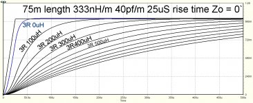
Here's a simulation for a nominal 75m length cable, showing the latency arising from the cable into 3R + a range of load inductances from 0 to 1mH. Params marked up on the image.jneutron said:My work involves running 50 to 75 meter long parallel pair cables to loads running in the 1 to 3 ohm range and 5 mH to 100 uH depending on frequency.
Its easy to see that even for a cable length more than an order of magnitude longer than domestic cables, load inductance dominates latency for a 25uS rise time.
Last edited:
No need, I understand it, just disagree. Yes the problems are conceptual, but they arise because of meaninglessness of TL terms when wavenumber is very small, not because of lack of understanding. As I've posted previously. I hit similar issues with Bateman's article 1st part, so not really interested in 2nd part unless there's a different approach. I am interested in the low impedance bridge in principle though.I'll try to find a good t line reference for you, and I'll also look for a good primer on what the settling time for a step function means, as you've still conceptually missed the boat.
- Status
- Not open for further replies.
- Home
- Member Areas
- The Lounge
- Speaker Cable lifters or stands?