Just in case anyone is holding their breath (or ordering popcorn) I have no intention of reviving my fruitless discussion with jn on this matter. Interested people can use the search function.
edit:why would anyone hold their breath waiting for you??
I would quote Dirty Harry, but you already know..
Come on it was fun. 😀 After all there is only one answer.
And you already knew it, as you edited in..
Using a t-line analysis provided a close approximation to the single stage LCR model. You showed this what, years ago?
To get very close, about 200 stages of lumped elements is needed. This from Cyril Bateman.
To have a good understanding, it is important to distinguish between models, where they are appropriate, and how to apply them.. For example, the LCR model does not simply provide the settling time cusp that a t-line model displays.
To discount a model because one feels like it is not how engineers or physicists should work. You understand this.
Some, like DF, will ignore without learning. Such is life..but I will admit, he is not a bad guy, very smart..
jn
Last edited:
so, to further chum the water, do I need to cryo-treat those Oregon Douglas Fir cable lifters, or will Ennemoser C37 and Peter Belt foil treatment be sufficient?
really, some of this stuff is just too much fun to ignore - I wish the OxyClean pitch man was still around
but wait, there's more
really, some of this stuff is just too much fun to ignore - I wish the OxyClean pitch man was still around
but wait, there's more
I'd go with the foil.so, to further chum the water, do I need to cryo-treat those Oregon Douglas Fir cable lifters, or will Ennemoser C37 and Peter Belt foil treatment be sufficient?
really, some of this stuff is just too much fun to ignore - I wish the OxyClean pitch man was still around
but wait, there's more
What's with the oxy guy...he selling cable lifters too??
jn
so, to further chum the water, do I need to cryo-treat those Oregon Douglas Fir cable lifters, or will Ennemoser C37 and Peter Belt foil treatment be sufficient?
really, some of this stuff is just too much fun to ignore - I wish the OxyClean pitch man was still around
but wait, there's more
Get it right now, it's Oregon myrtle.
Why look for the complicated answer when the obvious is staring you in the face?
Cable lifters keep the wire high enough to stop electron thingys pooling in the bottom of the loops during quiet moments and gives them a straighter path to follow, less steep gradients to climb. Works well for railways don't it? 🙄
Cable lifters keep the wire high enough to stop electron thingys pooling in the bottom of the loops during quiet moments and gives them a straighter path to follow, less steep gradients to climb. Works well for railways don't it? 🙄
Lots of popcorn!
I'll venture this: people will hear a difference between substandard el-cheapo zip-cord and a “engineered” cable of substantially lower linear resistance, as a rule. Will they really hear the difference between a hank of $1,000 a meter silver Litz-braided cable and some good heavy copper? My very careful A-B tests … show not: but for a particular case… when both are engineered to have very low end-to-end resistance and very low capacitance.
Some “appeal to the sophisticates” engineering is counterproductive, in that it really is designed to look sophisticated, unusual, special, but ends up introducing parasitic losses which just don't help the underlying demand for lossless (perfect case) transmission. One example was with a speaker cable built from one guy's bright idea to utilize (once-)common 25 pair telephone cord (remember that ubiquitous grey stuff?) as a kind of 50 wire Litz. The highs got pretty well washed out. Why? Well, it wasn't a bad idea, except that he got it in his head that every one of the 25 pairs needed to carry the compliment (+ and - output), then be stripped and soldered at the ends accordingly. HUGE series capacitance. The amplifier had to work hard just to keep up with the capacitive loss path. And failed.
I think the nearest thing to a perfect speaker cable would be a single 50 wire ribbon cable, with the left 25 and the right 25 wires shorted at the ends to make a 1 pair cable. Using the formula [gaugeeff = gaugeper - 10log₁₀( count )], the 26 gauge nominal per-wire copper becomes 12 gauge or so. And better than 12 gauge because each wire is far smaller than the skin effect depth (about 0.4mm at 20 kHz for copper). Moreover, having the flat cable maximally separates the conductors while utilizing a common material (ribbon cable). Ugly, perhaps. But in our trial, it did at least as well as ANY high end cable. Cheap, too.
Well, there's something more to add to the mix.
Resistance and capacitance. And I suppose inductance too, if a cable is particularly hackneyed in that direction. minimizing these. With overall impedance hopefully sought below 2% of the ohmage of the speaker. Or less. Hopefully less.
GoatGuy
Last edited:
Works well for railways don't it? 🙄
I didn't know railways had an electron pooling problem. That would explain a lot.😀
jn
Last edited:
Lots of popcorn!
I'll venture this: people will hear a difference between substandard el-cheapo zip-cord and a “engineered” cable of substantially lower linear resistance, as a rule. Will they really hear the difference between a hank of $1,000 a meter silver Litz-braided cable and some good heavy copper? My very careful A-B tests … show not: but for a particular case… when both are engineered to have very low end-to-end resistance and very low capacitance.
The tradeoff between inductance and capacitance is :LC = 1034 times about 4~5. L in nH per foot, C in pf per foot. With coax and striplines, it is 1034 times the relative dielectric permittivity. Plastics typically 3 to 4, foams 1.05 to 1.5.
Actually, it's significantly deeper than that. The exponential depth approximation is not valid at audio and wires at normal speaker cable size. It was derived for planar penetration on flat surfaces, bessels are more appropriate for wires but are far more complex.And better than 12 gauge because each wire is far smaller than the skin effect depth (about 0.4mm at 20 kHz for copper).
jn
I didn't know railways had an electron pooling problem. That would explain a lot.😀
jn
They have signs and stuff, beware high voltage etc. Wonder if they are short of cable lifters cos i keep hearing about a 'live rail' and how it's not good for the health to touch it 😱
Why is it a
Can your system convince you you're listening to a real piano?
?What a load of s*****
Can your system convince you you're listening to a real piano?
Get it right now, it's Oregon myrtle.
the cable lifters are fir,
Multi Blocks

The Golden Cuboids are myrtle
still trying to figure where / how to use themGolden Cuboids are made from America's most beautiful hardwood, the legendary Myrtle tree. Laser engraved with the Cardas logo.
Rarest of all woods, this symmetrical, broadleaf, evergreen Myrtle grows only in Southwestern Oregon's Coos and Curry counties.
Myrtlewood has a very complex grain structure. The coloring of the wood is unique, varying from a sedate, satiny gray to riotously, multicolored grains of red, yellow, and brown, with many burls and shapes in its grain. Denser than Oak, unseasoned Myrtle logs will not float.
nothing against his products - love the quad eutectic solder
of course, a simple google search would contradict the "rarest of all woods" statement
A huge amount of the current mess in the audio world has occurred precisely for this reason - which means it's good to get back to basics. Ignore "what's supposed to be ..." and do some casual experiments, with an open mind ... it's just possible one might find something interesting ... 😉Unfortunately, in the intervening time, much has been lost, ignored, or simplified to the degree that actual understanding and application to the real world has suffered. And, it allows pseudoscience a back door.
of course, a simple google search would contradict the "rarest of all woods" statement
Did a long time ago. Charles Hansen was the one who said the myrtle blocks as lifters would literally "bring the wife out of the kitchen".
Hallelujah ... after Scott's comment I went a-searchin' ... and it's already been done to death in dA - Charles most certainly "gets" it and this post, http://www.diyaudio.com/forums/lounge/146693-john-curls-blowtorch-preamplifier-part-ii-1351.html#post2631138, nails it!
I've been there so many times, over the years - talk about frustration! - that post alone beautifully encapsulates where the "craziness" of this whole business is ... unless one gets full control over what's going on here then this sort of "madness" keeps on happening ... 🙁 .
I've been there so many times, over the years - talk about frustration! - that post alone beautifully encapsulates where the "craziness" of this whole business is ... unless one gets full control over what's going on here then this sort of "madness" keeps on happening ... 🙁 .
Last edited:
Wow, that is a gorgeous wood, rarest or not. It's just a shame that tree probably lived 500 years or more, just to have some gooch fashion it into a hunk of bull ****.
If you want gorgeous, try this ... http://www.aussiewoodart.com/images/Huon Pine Erosion Bowl-1.jpg
Oh yeah, that's nice. That's one of those things that makes you want to redecorate around it, though. 🙂
On transmission lines at audio frequencies, Jim Brown writes:
The full equation for characteristic impedance is:
ZO = [ (R+j2πfL) / (G+j2πfC) ]1/2
At high frequencies (that is, f is large), (2πfL) is much larger than R, and (2πfC) is much larger
than G. So at high frequencies, the equation becomes simply:
ZO = [ j2πfL) / j2πfC) ]1/2 and further simplifies to ZO = [ L/C) ]1/2
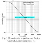
which is the familiar equation. But what if f is not large? Fig 1 shows the impedance of a typical
coaxial cable at audio frequencies using the full equation. Why the wide variation? Because
at low frequencies, R is much greater than 2πfL, and 2πfC is much greater than G.
Thus, at low audio frequencies, the equation simplifies to ZO = [R/j2πfC]1/2. Within the audio
spectrum and for a decade or so above it, R in this equation is simply the DC resistance of
the cable(per the same unit length as the L and C parameters). This causes the impedance to
be quite high and predominantly capacitive near zero frequency. As frequency increases, L
becomes significant, and ZO transitions to the familiar 50-100 ohm impedances at high frequencies.
And the transition occurs right in the middle of the audio spectrum! Through the
transition region, the "j" term causes ZO to be a combination of resistance and capacitance.
[Although the data presented here is for coaxial cables, virtually all commonly used cables,
including twisted pairs, exhibit these characteristics!]
from:
"Transmission Lines at Audio Frequencies, and a Bit of History"
by Jim Brown
Audio Systems Group, Inc.
http://www.audiosystemsgroup.com/TransLines-LowFreq.pdf
The full equation for characteristic impedance is:
ZO = [ (R+j2πfL) / (G+j2πfC) ]1/2
At high frequencies (that is, f is large), (2πfL) is much larger than R, and (2πfC) is much larger
than G. So at high frequencies, the equation becomes simply:
ZO = [ j2πfL) / j2πfC) ]1/2 and further simplifies to ZO = [ L/C) ]1/2
which is the familiar equation. But what if f is not large? Fig 1 shows the impedance of a typical
coaxial cable at audio frequencies using the full equation. Why the wide variation? Because
at low frequencies, R is much greater than 2πfL, and 2πfC is much greater than G.
Thus, at low audio frequencies, the equation simplifies to ZO = [R/j2πfC]1/2. Within the audio
spectrum and for a decade or so above it, R in this equation is simply the DC resistance of
the cable(per the same unit length as the L and C parameters). This causes the impedance to
be quite high and predominantly capacitive near zero frequency. As frequency increases, L
becomes significant, and ZO transitions to the familiar 50-100 ohm impedances at high frequencies.
And the transition occurs right in the middle of the audio spectrum! Through the
transition region, the "j" term causes ZO to be a combination of resistance and capacitance.
[Although the data presented here is for coaxial cables, virtually all commonly used cables,
including twisted pairs, exhibit these characteristics!]
from:
"Transmission Lines at Audio Frequencies, and a Bit of History"
by Jim Brown
Audio Systems Group, Inc.
http://www.audiosystemsgroup.com/TransLines-LowFreq.pdf
Attachments
I know that GFK has long departed, due to the hostile tone of the nay-sayers in this thread! 😱
When you work with microwaves, inductance and capacitance take on a physical meaning in terms of bits of different sized waveguide hooked together. You use 2x2 scattering matrix methods to work out reflections from abrupt changes of size and termination: Transfer matrix | Physics pages
Like most real and exact mathematics, it even works in higher quantum theory. 🙂
No way do we need to know this with speaker cables. Probably lumped inductance and capacitance per unit length is near enough, as Jim Brown says.
But the fact remains, that if you terminate a cable with a near short, you see the inductance. If you terminate near open circuit, you see the capacitance. Simple as that. So let's MATCH things as much as we can! It always works better.
There is a branch of science called Information Theory. This relates signal to noise ratio and bandwidth to the capacity of a system for carrying information.
It's one of those brilliantly general theories, thought out by Claude Shannon, where the precise details don't matter to lead you to optimal solutions. One of its interesting predictions, is that the source should be matched to the load in terms of frequency response for maximum capacity. Matched Filter.
Isn't that what we've been talking about really? 😎
If you want to try an off-the-wall experiment in matching, try connecting a 10W 50 ohm wirewound resistor across the speaker input. It sounds better! 😕
- Status
- Not open for further replies.
- Home
- Member Areas
- The Lounge
- Speaker Cable lifters or stands?