OS,
Do you have any idea why the spook is putting out 3db more on the bottom end? That seems like a big difference in the FR between the two units.
Do you have any idea why the spook is putting out 3db more on the bottom end? That seems like a big difference in the FR between the two units.
OS,
Do you have any idea why the spook is putting out 3db more on the bottom end? That seems like a big difference in the FR between the two units.
According to my measurements , it's not. But in listening , one gravitates toward
lowering <100hz ??
Perhaps ... this is why spooks are also used as sub amps ? (common complimentary
in most small plate amps).
I have not done the ND , carl. I have no indoor shop ... so many projects are
being done on my deck now (in the warm sun - finally 🙂🙂🙂)
I'll be back on audio after they are done.
Krisfr , when I make the full manuals - BOM will be included.
For now , use the schema. Many of the spook components are
non-critical up to 20% ... as long as the positive part matches the
negetive. Spook input pair semi's like to be at least DMM Hfe matched,
but the CCS trimmers and servo will ultimately correct any offset.
(longer for the servo to "settle without matching).
OS
How long has the "spook" been in development? The good professor Marshall Leach on LOWTIM changed parts and transistor topology for 3 years after the article appeared in AUDIO. But I guess he did not have PC simulation and only fortran and a mainframe that he had to get in line to use. I changed parts until pads started lifting from the boards due to over heating, virtually every part on the board. Have you done any tests that show the odd harmonic poles in "spooky" (DIM100, SMPTE???). Very interested in building! Thank you OS for your hard work! Ray
Have you measured phase angle? Thanks, Ray
You mean group delay ?
Or the phase margin at unity gain ?
OS
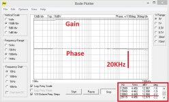
Thanks, Yes, phase shift at 20K. A graph would be great across bandwidth. Great work OS and thanks Valery! Ray
What expression would plot that ?Pete, my understanding - Ray means the phase response, e.g. phase shift at 20KHz. I normally measure it for my amps (example for CF-FET V2.0 is attached).
Ray, am I right?
OS
My small 2 cents. IPS with singleton CFP input and CFP VAS, sound is beautiful as for the simple circuit.
That is a killer little circuit , borys !!
Simulates wonderful - and man ... SIMPLE !!
OS
That is a killer little circuit , borys !!
Simulates wonderful - and man ... SIMPLE !!
OS
How about DC Offset stability from temperature?
What expression would plot that ?
OS
I'm not sure how to plot it in LTSpice 🙂
In Multisim - Bode Plotter does this.
The one I attached is a real life measurement, done with my Velleman oscilloscope / generator combo >PCSGU250<
My small 2 cents. IPS with singleton CFP input and CFP VAS, sound is beautiful as for the simple circuit.
Hi borys,
What is type/spec. of the led you use?
Marc
OS
Thanks.
There is a way of bit further improvement in % nubers but the H2 H3 ratio is getting a bit worse (more H3 and less H2).
bimo
The temperature-wise it is ok to leave it like this, after I set the offset it is changing by 50mV, I will try to work it out later.
Idefixes
The standard 3mm LED (in my case orange), there is approx 1,8V across it, so 1,8-0,65V = 1,15V /220R = 5,2mA in VAS. If you use some different LED should make nearly no diffrence.
I am making the CFP-OPS for that front end (I have made prototype on single board before and was very good soundvise).
Singleton with CFP at the input is very cool. I have also tested a pretty similar topology, but with jfet/bjt CFP combination and cascoded VAS. As soon as both CCSs are thermally stable, there's no problem with DC offset drift at the output. But I a local oscillation in the input CFP initially - cured by additional cap.
Peter - cool design
Peter - cool design
Hi SlewMaster builders!
I need some help to speed up the assembling process of documents. Helping the choose of right IPS, need to assemble the "The Slewmaster series" pdf with the following content:
- The Slewmaster series
- History
- Technology
- SlewMasters in audio chain
- Comparison table
- Which one should I bulid?
- Listening impressions
All the necessary info and further suggestions are welcome.
Thank You
Best Regards
egra
Attachments
If someone has an assembled OPS and OPS, please take some photo on it with similar POV that can be seen in the attached preview. The assembled PCB without cables would be great. Please don't use flash, and try to avoid the depth of field blur (ie. Wide angle lenses "short focus", and bright room)
I had "built" my own version of Spooky which can be seen on cover of SM series pdf 🙂
egra
I had "built" my own version of Spooky which can be seen on cover of SM series pdf 🙂
egra
Attachments

Last edited:
- Home
- Amplifiers
- Solid State
- Slewmaster - CFA vs. VFA "Rumble"