I've used some Alps pots with built in on/off switch to get around the popping problem. Worked very well.
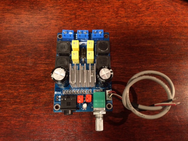
NI just got one of these amps from Amazon for $20. SMAKN® TPA3116 Amplifier Board(50W+50W) D Class Amplifier Board:Amazon:Electronics A very neat looking well built unit with some features that may be unique in such a small package. Here are some photos of the top and bottom side:

Observations:
1. The volume pot is high quality and includes a power off feature with a click when turned all the way left. Nice feature and doesn't seem to pop speakers either.
2. There is bright blue power LED that goes off when unit is switched off.
3. It has a nice solidly mounted heat sink that won't come off as the pins are soldered onto pcb.
4. It uses mostly SMT parts but has thru hole options on many like the input caps are 1uF 63V ceramic candy drop orange units which make upgrading easy.
5. It uses 22uH coils SMT style but underneath are thru holes in case you want to use radial lead coils.
6. It has correct value 0.68uF metalized poly film caps on LC filter.
7. It does not have any RF snubber after the LC filter! Nor does it have bootstrap snubber. However, there is plenty of access on bottom side for adding either axial lead or SMT bootstrap snubber.
8. There is a spot for adding a 7805 voltage regulator and 5v output solder pad.
9. There are numerous open solder bridge points for effecting options such as PBTL mode and others which I don't know as they are labeled in Chinese on the PCB. Maybe someone can translate for me. I see a gain setting of 26dB vs 36dB silk screened on bottom. Wonder how to change that via solder bridge points?
10. There is both 3pin (with cable) and 3.5mm stereo jack inputs.
11. The positive and negative terminals on the speaker outs are mirror image +/- , -/+ and are CORRECTLY labeled.
12. There is a input protection diode that is bypassabe with solder bridge point.
13. There are many solder pads for SD, Mute, etc.
14. The parts quality in general looks good and soldering quality and craftsmanship are clean. No ugly looking joints or sloppy skewed parts.
I have not had a chance to test extensively but initial listening with a full range Dayton RS100-4 in an XKi enclosure sound good. I will have to put on my reference system and measure response compared to my DUG v0 amp to see if it looks good. So far it seems like a great value and would be ideal for mods on many components. My concern is lack of RF snubber on output. Similar to a YJ blue black Danzz amp, the coils are slightly warm at idle even.
Looking for feedback from others who may have tried this and help with PCB text translation.
Correction - Irrebeo pointed out that the input caps are actually Pilkor metallized polyester caps.
Last edited:
I ordered a board very similar yesterday!
Looks to have some different parts from yours, but exactly same design. Mine was $12 though...
PS. I could help with the Chinese, but the included pics are both top ones.! 😉
Here's the one I ordered:
URL please.
NI just got one of these amps from Amazon for $20. SMAKN® TPA3116 Amplifier Board(50W+50W) D Class Amplifier Board:Amazon:Electronics A very neat looking well built unit with some features that may be unique in such a small package. Here are some photos of the top and bottom side:
Observations:
1. The volume pot is high quality and includes a power off feature with a click when turned all the way left. Nice feature and doesn't seem to pop speakers either.
2. There is bright blue power LED that goes off when unit is switched off.
3. It has a nice solidly mounted heat sink that won't come off as the pins are soldered onto pcb.
4. It uses mostly SMT parts but has thru hole options on many like the input caps are 1uF 63V ceramic candy drop orange units which make upgrading easy.
5. It uses 22uH coils SMT style but underneath are thru holes in case you want to use radial lead coils.
6. It has correct value 0.68uF metalized poly film caps on LC filter.
7. It does not have any RF snubber after the LC filter! Nor does it have bootstrap snubber. However, there is plenty of access on bottom side for adding either axial lead or SMT bootstrap snubber.
8. There is a spot for adding a 7805 voltage regulator and 5v output solder pad.
9. There are numerous open solder bridge points for effecting options such as PBTL mode and others which I don't know as they are labeled in Chinese on the PCB. Maybe someone can translate for me. I see a gain setting of 26dB vs 36dB silk screened on bottom. Wonder how to change that via solder bridge points?
10. There is both 3pin (with cable) and 3.5mm stereo jack inputs.
11. The positive and negative terminals on the speaker outs are mirror image +/- , -/+ and are CORRECTLY labeled.
12. There is a input protection diode that is bypassabe with solder bridge point.
13. There are many solder pads for SD, Mute, etc.
14. The parts quality in general looks good and soldering quality and craftsmanship are clean. No ugly looking joints or sloppy skewed parts.
I have not had a chance to test extensively but initial listening with a full range Dayton RS100-4 in an XKi enclosure sound good. I will have to put on my reference system and measure response compared to my DUG v0 amp to see if it looks good. So far it seems like a great value and would be ideal for mods on many components. My concern is lack of RF snubber on output. Similar to a YJ blue black Danzz amp, the coils are slightly warm at idle even.
Looking for feedback from others who may have tried this and help with PCB text translation.
xrk,
So you got one of this too. I put in a brief review on the same amp back in January (post 6419).
I have listening to this amp for 2 months now, it sounds good in my setup, definitely better than the original YJ red.
I can read Chinese but the labels on the bottom side of the PCB are not sufficiently clear. You probably have to do some reverse engineering to figure out how to play with those connection points.
My amp does give out a light pop when turn on using the switch in the pot.
I agree with you, the soldering was quite well done as compare to the typical EBAY stuffs. What I found interesting was that after the lead of the thru hole component was cut off, they bent what's left of the lead towards the pcb and placed a tiny piece of an insulator (my guess) between the lead and the pcb.
I bought from the "original designer" at TB (for about 7US$, shipping was extra), the gain was actually set at 32 db and I like it.
The blue LED is really too bright for my taste. I will never forget turning off the amp.
I wish there is a version without the pot, like the Audiobah green or your "weiner". Currently, I turn the pot full on and use my TVC for volume control. This amp manufacturer does sell a PBTL version for use with subwoofer.
This amp sounds clean and quiet, the base response goes quite low (my speakers' manufacturer claimed -3dB at ~25 Hz in room) and I can hear it in some records. This amp performs better than the YJ's. At this price, and I can recommend it without any reservation
xrk,
OK, I can decipher part of the instructions.
To change over to PBTL, break S1 and join S2 to S6. If you look closely at each of the S connections, you can actually see two little solder spots at each point. "My interpretation" is you just have to join them with a tiny bit of solder which is easy. However, to break S1 may no be so. The two spots are just too close Please do not hold me responsible if bad things happen.
I have no idea what "PC mode" means. I think PSW is just the power switch.
I am thinking of doing the snubber mode too. But since the amp sounds fine at this point, there is not big incentive.
Regards,
xrk971, I'm using that excact amp in my Creative pc speakers 🙂. Unfortunately it suffers from some hiss stock when used for nearfield listening.
I did the analog power in RC mod on it and it went quiet! Other than that it's really good!
I did the analog power in RC mod on it and it went quiet! Other than that it's really good!
regulated power for the AVCC pin
I attached the typical application schematic from the DS.
I need some help to calculate the values for a power supply for the AVCC pin of the TPA chip. I am aiming for 19 V. My incoming supply is 22 V .
I can build another power to get higher incoming V if necessary.
Is it better to use this after a LM 317 regulator ?
thanks
kp93300
Attachments
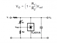
If you make R1 = 10k and R2 = 1.5k you'll get about 19.2V across the TL431. You can use an LM317 as a current source in place of the unmarked resistor in that schematic, however as you have only 22V going in this might be getting a bit close to its drop-out voltage. Is your 22V regulated in any way?
I wish there is a version without the pot, like the Audiobah green or your "weiner". Currently, I turn the pot full on and use my TVC for volume control. This amp manufacturer does sell a PBTL version for use with subwoofer.
Lo_Tse,
Thanks for the translation - I figured out most of it just by studying the traces. If you look underneath the pot, you will see a couple of spots that allow you to add a solder bridge to bypass the pot volume. The power will still work (and can be by-passed too). This board is full of optional solder bridge connections. I don't think anyone else makes a board with this many options for solder bridging. I agree it sounds quite good.
I may proceed with the usual Panasonic OSCON's, and bootstrap snubber, swap input caps to 3.3uF polyfilms. I like how compact this unit is - and equipped with 3.5mm or flying lead audio inputs lets one use it inside active speakers or as mp3 player station.
Can't easily answer that until I know the variations on your 22V rail. Also the TPA3116 DS doesn't mention the current requirement at the AVCC pin so its going to be suck-it-and-see. First up I'd aim for 20mA so with a 2.8V drop the R value will be 130ohms.
How are you getting 19V for your main rail (the one going to PVCC)? According to TI's advice there should be almost no difference in the voltage on the two rails. If you're using another regulator for that PVCC then I'd suggest diodes between the two to maintain TI's stipulation.
How are you getting 19V for your main rail (the one going to PVCC)? According to TI's advice there should be almost no difference in the voltage on the two rails. If you're using another regulator for that PVCC then I'd suggest diodes between the two to maintain TI's stipulation.
If you make R1 = 10k and R2 = 1.5k you'll get about 19.2V across the TL431. You can use an LM317 as a current source in place of the unmarked resistor in that schematic, however as you have only 22V going in this might be getting a bit close to its drop-out voltage. Is your 22V regulated in any way?
Hi abraxalito,
I pvcc power comes from a Lm 338 regulator.
Last edited:
According to TI's advice there should be almost no difference in the voltage on the two rails. If you're using another regulator for that PVCC then I'd suggest diodes between the two to maintain TI's stipulation.[/QUOTE]
Can you show to place the diodes ?
Can you show to place the diodes ?
So the PVCC rail is 22V coming from LM338? If so then seems AVCC can't be 19V - too large a difference according to TI. You need to get them nominally the same voltage - meaning your shunt reg should be powered from the input to the LM338, not its output.
Either set both AVCC and PVCC to 22V or both to 19V.
Either set both AVCC and PVCC to 22V or both to 19V.
Is this better?
Quite!
Lo_Tse beat me to it. The only thing I'm not sure is if you want to use mono, do you have to solder S2 to S6 or just S2 and S6 alone.
Also, there's a warning on the side that says you have to connect speakers first, then power, otherwise it will create a short.
So the PVCC rail is 22V coming from LM338? If so then seems AVCC can't be 19V - too large a difference according to TI. You need to get them nominally the same voltage - meaning your shunt reg should be powered from the input to the LM338, not its output.
Either set both AVCC and PVCC to 22V or both to 19V.
I mean both the AVCC and PVCC is now at 19 V dc. It is 22 V before the LM 338.
The V out from the LM 338 is adjustable .
I intend to feed the TL 431 with 22V and get 19.2 V out at the TL431 to feed the the AVCC pin.
thanks very much
Last edited:
I ordered this board during the Chinese New Year. It was only $9.90 shipped so I didn't mind the longer wait.
I hooked it to my favorite Class D board, the Sure TPA 3110 (with Oscons mod), I used my Astron PS to power both boards. This thing sounds pretty good, no noise, or hiss. It has bass, treble; balance; volume; loudness controls. Bass control is especially useful.
I then tried it in front of my cheap 6N3 tube preamp/Sure amp. The sound is smoother, warmer, and a little more to my liking. The balance control is useful, and the loudness control also works good. Currently using with my PC for music streaming. All in all so far I like this little board.
I think I will put it in a box with one of my TPA 3116 B/B boards to use as a portable with a couple of Bookshelf speakers I have. With the tone, and balance controls, it should be good for a portable system where speakers may not be placed in ideal locations.
Anyway - so far it was a a worthwhile $10 spent.

Lacro, I also bought similar 1036 tone board, but I have some problems, described in the post
I would appreciate any input how to solve my problem.
Thanks
Lo_Tse,
Thanks for the translation - I figured out most of it just by studying the traces. If you look underneath the pot, you will see a couple of spots that allow you to add a solder bridge to bypass the pot volume. The power will still work (and can be by-passed too). This board is full of optional solder bridge connections. I don't think anyone else makes a board with this many options for solder bridging. I agree it sounds quite good.
I may proceed with the usual Panasonic OSCON's, and bootstrap snubber, swap input caps to 3.3uF polyfilms. I like how compact this unit is - and equipped with 3.5mm or flying lead audio inputs lets one use it inside active speakers or as mp3 player station.
xrk,
Yup, I am surprised too that the board designer actually put in place a lot of flexibility. Thank you for pointing out the pot bypassing possibility.
Let us know what the results are after you done the mod.
Regards,
I mean both the AVCC and PVCC is now at 19 V dc. It is 22 V before the LM 338.
Since that 22V is before the regulator its being provided by a rectifier and some smoothing caps? In which case the 22V isn't going to be stable - it'll have some ripple on it in the short term and vary with mains voltage over the longer term. This means its not going to give enough headroom for your LM317 to work as a constant current source.
The V out from the LM 338 is adjustable .
I suggest setting it down to 18V to allow the LM317 to function as a CCS. The TL431 should also be set to 18V using 1k for the lower and 6.2k for the upper resistor.
- Home
- Amplifiers
- Class D
- TPA3116D2 Amp