Hey guys/gals. I can't seem to get much help on the Klipsch forums in regards to how to do this. I am trying to reassemble my Klipsch RF-3 crossovers on a piece of wood as the original circuit boards I accidentally fried. I'd rather not buy new ones from Klipsch, as they aren't economical for me at this point, and I just need to get these working with what I have.
Here is the schematic - https://community.klipsch.com/index.php?/topic/144465-crossover-schematic-for-rf3/
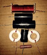
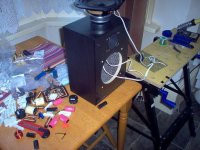
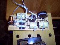
Here is the actual crossover compenents laid out very similar to how they looked on the circuit board - https://community.klipsch.com/uploads/monthly_03_2015/post-58896-0-59340000-1426597181.jpg
Here is the schematic - https://community.klipsch.com/index.php?/topic/144465-crossover-schematic-for-rf3/
Here is the actual crossover compenents laid out very similar to how they looked on the circuit board - https://community.klipsch.com/uploads/monthly_03_2015/post-58896-0-59340000-1426597181.jpg
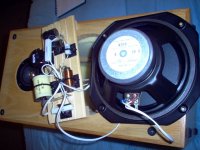
There's loads of ways to lay out a crossover on a piece of wood. It's a good choice IMO.
Tips and ideas Copyright 2012-14
I use tagstrip and cable ties, some prefer hot glue:
5 Way Tagstrip | Maplin
Coils at right angles, to reduce interference:
Placement of coils in crossover networks
15-30A tinned copper wire works well enough for little hookup connections. Fuse wire in other words!
Have a go. 🙂
Attachments


Last edited:
You use a crimping tool to attach speaker connectors to the wires. Woofer connectors are bigger than tweeter ones usually. Or hard solder.
Maplin Delux Crimp Tool Set | Maplin
If the wires aren't fat enough, you can double them back to make them fatter.
It's a bit dangerous to solder wires directly to fragile tweeters, but it can be done.
The speaker terminals on the back of the speaker cabinet are tough as old boots. I'd solder.
Maplin Delux Crimp Tool Set | Maplin
If the wires aren't fat enough, you can double them back to make them fatter.
It's a bit dangerous to solder wires directly to fragile tweeters, but it can be done.
The speaker terminals on the back of the speaker cabinet are tough as old boots. I'd solder.
Attachments
Last edited:
Actually what I mean is, I don't know exactly how the caps, resistor, coils ect all wire together. Which leads from which parts go to the drivers and which ones go to the speaker terminals? I'm just needing a bit of a hand hold through how I go about wiring this particular 2-way crossover. 🙂 If someone doesn't mind.
I am hoping you (or anyone on here) can give me a sort of "connect capacitor A to resistor B" and so on..
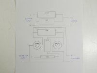
I've got to head out in a minute. But you start with the input signal to the crossover. You use a common earth, here the black striped wire. This is the left side of the crossover.
Then you do your filters, and you have an output for the woofer and the tweeter. Using a common earth point, where you see three wires meeting. Because the tweeter and bass share the earth in a parallel crossover.
It's hard to figure out initially, but you can physically lay out the components and work out how you're going to do it.
Must go now. 😱
Attachments
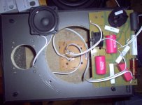

How do you determine + - polarity? Those pictures are a bit confusing for me, it appears you have everything wired up to a curcuit board, whereas I am just using a piece of pine board. I am just a bit confused as to which leads I have going to what. I know I need to solder the caps, inductors, coils, and resistors together, but also leave leads that can connect to + - cables going to the drivers and to the speaker terminals.
Sorry, I hope I'm making sense. :/
Sorry, I hope I'm making sense. :/
Last edited:
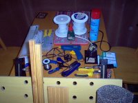
Blake, I am just showing you several ways to skin a cat! I use whatever comes to hand. 🙂
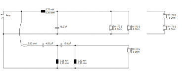
Now here's your schematic for a Klipsch RF-3 (or is ir RF-3ii?) which is twin bass and horn tweeter AFAIK.
It's gonna look like the 2nd order bass and 4th order tweeter filter below. I'm using an extra resistor in this case on the bass shunt. You won't need it.
I'd guess your 8 ohm basses are wired in parallel, but series with 4 ohm drivers is a possibility.
Attachments
Blake, I am just showing you several ways to skin a cat! I use whatever comes to hand. 🙂
Now here's your schematic for a Klipsch RF-3 (or is ir RF-3ii?) which is twin bass and horn tweeter AFAIK.
It's gonna look like the 2nd order bass and 4th order tweeter filter below. I'm using an extra resistor in this case on the bass shunt. You won't need it.
I'd guess your 8 ohm basses are wired in parallel, but series with 4 ohm drivers is a possibility.
I really appreciate the help! 🙂 Any additional input to explain it in a step by step fashion is more than welcome! 😀 Did you draw up that diagram?
crossover is shown with input to the network on the left side of the drawing and connection to the drivers on the right side of the drawing. In this drawing the woofer section of the network is on the top of the drawing and it shows a laminate (steel) core inductor in series with the woofer(s) and a capacitor (polarized) across the woofer(s). Hope that helps some.
Attachments
Last edited:
I really appreciate the help! 🙂 Any additional input to explain it in a step by step fashion is more than welcome! 😀 Did you draw up that diagram?
Yes, I did, I drew up the crossover in Boxsim. I also looked at how it worked with some allowances for a recessed horn tweeter. You can also import some metal woofered designs like this into the projekte folder:
boxsim-db.de | Boxsim Projektdatenbank
It's quite a deep hobby with a lot of science attached. If you want to go the whole hog. The idea is the woofers do the low frequencies, and the tweeter does the high frequency. 🙂
TBH, I find laying out crossovers hard myself. But it's essentially following a wiring diagram. So far, so good. I haven't blown up my amplifier. 😀
crossover is shown with input to the network on the left side of the drawing and connection to the drivers on the right side of the drawing. In this drawing the woofer section of the network is on the top of the drawing and it shows a laminate (steel) core inductor in series with the woofer(s) and a capacitor (polarized) across the woofer(s). Hope that helps some.
I thought all the parts were non-polarized...?
I thought all the parts were non-polarized...?
In this instance yes they are NP caps but very often with bass sections you are dealing with large value capacitors which would only fit the available space if they were electrolytic and so polarization is always given so you can insure the cap is installed in the right direction.
Film capacitors and inductors are both wound and though you can connect them in any direction (orientation) that you like and they will work they will always sound better if you install them the right way. This is easy to see on most coils but can be impossible to see on a cap unless identified by the maker. With a coil you want the incoming signal to enter the wire leading to the centre of the coil and come out of the coil on the outer most loop or winding. This provides shielding of a sort. The same is true with wound foil capacitors but if not identified you can do one of two things ask the manufacturer or install them in a working circuit one at a time and listen to them in both directions. Most people are simply not that interested to go to this effort with capacitors but they will spend hundreds of dollars for a single cap and happily install it backwards. As luck would have it with capacitors you have a 50% chance of getting it right no matter which way you install it. Hope this helps.
When it comes to film capacitors Polyester is fairly robust as far as heat goes when soldering goes as you move into the more exotic varieties they generally get a lot more sensitive to heat and are more easily damaged the most sensitive are Polystyrene. You need to use heat sinks with those and they are a very good idea for learners on any foil cap. A good soldering iron is a must as well one with adjustable heat is the best to buy. When you solder you hold the tip to the lead to be soldered and you heat the lead with the iron when hot enough you melt the solder on the heated lead NOT on the iron. If the solder won't melt on the lead it is not hot enough and needs more heat. Good irons not only have the ability to get to the exact right temperature and maintain it but they can also deliver a lot of heat quickly even into large wires because they have a lot of thermal capacity. Soldering guns and large irons and especially little irons (which can do some of the very worst damage) are best avoided. You can practice your soldering skills for free on old dead components which can usually be had for the asking. Best regards Moray James.
PS: there are lots of you tube tutorial videos that you can watch also. Some will be better than others but they should help you a lot.
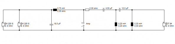
Blake, I have redrawn your schematic so you might work out how to lay it out.
It's extremely close to the circuit I show, which merely has an extra resistor in series with the bass capacitor to damp a peak at crossover. A common enough technique.
Edit. Oh, that 0.2mH should be 0.25mH. Whatever. LOL
It's extremely close to the circuit I show, which merely has an extra resistor in series with the bass capacitor to damp a peak at crossover. A common enough technique.
Edit. Oh, that 0.2mH should be 0.25mH. Whatever. LOL
Attachments

Last edited:
So I upgraded all the caps to some nice Dayton caps, the resistors are Mills high quality ones. Should I upgrade the inductor and coils?
Yes, that's even clearer, this is a massive help! Thank you guys so much for all the help and hand holding. 😛 🙂
Should I place one of the air core coils at a right angle to avoid interference?
Should I place one of the air core coils at a right angle to avoid interference?
Yes, that's even clearer, this is a massive help! Thank you guys so much for all the help and hand holding. 😛 🙂
Should I place one of the air core coils at a right angle to avoid interference?
that would help. Coils need to have a common centre axis when you do this if you want to have symmetrical cancellation.
- Status
- Not open for further replies.
- Home
- Loudspeakers
- Multi-Way
- Help wiring my Klipsch RF-3 ii crossover