When using a choke input filter after a rectifier, some people prefer a multi-section filter, for example, L C L C: 5h-20u-5h-20U because it should reduce hum more than the same total L and C quantities used in a single section LC filter such as L C: 10H-40U.
Because the critical inductance depends on the minimum current to be drawn, it seems better for overall regulation when the minimum current is small, to use the singe section filter and put all the inductance before any capacitor filtering.
This would be for anode supply of class AB circuits having a low idling current, and in instrument-type regulated power supplies that have a wide range of load current. It should help to keep the no-load voltage from rising so much.
Parts on hand for this project are two 5H inductors and two 20uF capacitors. How to arrange them?
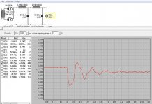
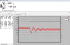
The chart shows data from PSUD for a proposed high voltage supply. The program was run using constant current loads from almost zero to 2A.
It shows that a single 10H choke followed by a 40uF capacitor gives better voltage regulation at lower currents (0.25A) than a two section filter mad of two 5H chokes and tow 20uF capacitors.
I hope this makes sense. I wish I had a 20H choke or higher that would take the current.
Because the critical inductance depends on the minimum current to be drawn, it seems better for overall regulation when the minimum current is small, to use the singe section filter and put all the inductance before any capacitor filtering.
This would be for anode supply of class AB circuits having a low idling current, and in instrument-type regulated power supplies that have a wide range of load current. It should help to keep the no-load voltage from rising so much.
Parts on hand for this project are two 5H inductors and two 20uF capacitors. How to arrange them?
The chart shows data from PSUD for a proposed high voltage supply. The program was run using constant current loads from almost zero to 2A.
It shows that a single 10H choke followed by a 40uF capacitor gives better voltage regulation at lower currents (0.25A) than a two section filter mad of two 5H chokes and tow 20uF capacitors.
I hope this makes sense. I wish I had a 20H choke or higher that would take the current.
Attachments

LCLC would give steeper slope for noise rejection than LLCC, but LLCC frequency starts lower and has a more predictable behavior.
LLCC would give lower impedance at the PSU output than LCLC, because there is more C that isn't blocked by the L. In fact I wonder if the middle C would even be much useful to the load.
So yea, it's a trade off between noise and impedance. When noise is important and high impedance is no issue, go nuts with the LC train. But for a power supply where impedance matters, stuff as big a capacitor you can at the output and make sure the impedance upstream is low enough to feed the caps without the voltage going all 120Hz wavy.
Anyway I might have missed something, what is the y axis on the graph? Voltage? How are you measuring the voltage: peak or average or?
Last edited:
A useful graph. Might help reduce all the confusion which seems to be around on choke input supplies.
Might be useful to add another line to the graph: same components arranged as a cap input PSU.
Might be useful to add another line to the graph: same components arranged as a cap input PSU.
A good technique, if your make your own chokes, is to mount 2 or 4 of the blades to short the airgap: that way, the inductance at low currents will be much larger, for example 20H for a nominally 5H one, but it will quickly saturate at higher current, reverting to 5H.
That way, you'll get the best of both worlds: a 4th order filtering with a good regulation down to low currents, and as a bonus, very much reduced ripple under quiescent conditions, where it generally matters most
That way, you'll get the best of both worlds: a 4th order filtering with a good regulation down to low currents, and as a bonus, very much reduced ripple under quiescent conditions, where it generally matters most
chokes with 2 coils
Hello,
Slightly off topic. I have 2 lundahls double coil chokes that i wanna use for a choke input filter ( LL2733 and LL1694)
If i wire them according to the Lundahl pdf files i will get the following '' situation
Rectifier-outer winding coil one -inner winding coil one -solder bridge- inner winding coil two-outer winding coil two- first capacitor.
The other choke it is inner outer outer inner.
Which one will give the best results.
Greetings, Eduard
In both cases, these PSUs will ringing like crazy.
Not good
...make no-ringing conditions and then measuring.
Member
Joined 2009
Paid Member
A good technique, if your make your own chokes, is to mount 2 or 4 of the blades to short the airgap: that way, the inductance at low currents will be much larger, for example 20H for a nominally 5H one, but it will quickly saturate at higher current, reverting to 5H.
That way, you'll get the best of both worlds: a 4th order filtering with a good regulation down to low currents, and as a bonus, very much reduced ripple under quiescent conditions, where it generally matters most
Has anybody tried this suggestion, it sounds like a rare free lunch opportunity ?
This idea is not new. There have been specially shaped ferrite cores around for "saturable inductors"
- Home
- Amplifiers
- Power Supplies
- Illustration of critical inductance