Amps are usually unbalanced output, which means live and earth. We should be using coaxial 8 ohm
The twisted pair is a good choice for coupling single ended stages and /or speakers as common mode noise can be isolated from the signal.
With the load referenced to the signal source through one signal current path, the load stage floats upon common mode cable noise preventing common mode current from flowing. The differential signal currents establish their AC reference across the load independently.
If the load needs to be referenced to the driver stage a guard can be tied to this reference along with one of the twisted pair.
Some use coax with the shield to the lower impedance terminal. If there is one current path, impedances are in series, and coax will allow differential mode noise.
I don't know what you are talking about, SY.
Since you've been told again and again that characteristic impedance is irrelevant and why (wavelength) but you're still carrying on about it, I really don't know what else to say.
I gave you the hint you need to understand why your statement about reflections was generally incorrect. I think you're a resourceful enough guy to study a bit and figure out why that is so.
The Radio Frequency Characteristic Impedance formula:....................................................
Let me tell you what I know about Characteristic impedance - Wikipedia, the free encyclopedia. Every low resistance cable has a certain capacitance and inductance per unit length. The characteristic impedance is just Root L/C. You can make very small 75 ohm cables, or very fat ones. It's just a question of the ratio of the dimensions of the conductors being kept constant. Fatter ones will have lower losses in practice.
......................................
None of which solves the problem here, but the science of cables is real. And worth knowing, IMO. 😎
ZO = [ L/C) ]1/2
is a simplified formula that only works at radio frequencies (say ½MHz and up).
The complete formula is:
ZO = [ (R+j2πfL) / (G+j2πfC) ]1/2
Jim Brown has an excellent paper explaining the whole thing:
"Transmission Lines at Audio Frequencies, and a Bit of History"
The behavior of cables at audio frequencies is widely misunderstood. This tutorial attempts to shed some light and bring some sanity to the discussion.
http://www.audiosystemsgroup.com/TransLines-LowFreq.pdf
*************************
About 50 more Jim Brown papers:
Audio Systems Group, Inc. Publications
Anyone consider that maybe cable risers may be useful to avoid interference from wiring routed beneath the floor such as power wires feeding wall outlets and lighting??? Some wiring can be mounted to floor joists below the subfloor which could interfere with speaker wires laid directly on the floor.
I looked over the Wikipedia page, it seems to be missing the part about when the wavelength is substantially shorter than the cable. But maybe system7 will believe this guy who wrote this authoritative tutorial. Check out page 42, Termination for Video and RF:You left out the part about "irrelevant to audio frequencies."
http://www.bennettprescott.com/downloads/grounding_tutorial.pdf
I looked over the Wikipedia page, it seems to be missing the part about when the wavelength is substantially shorter than the cable.
That could be because the person who wrote the Wikipedia article assumed the reader had the knowledge to put the article into the proper context.
Characteristic impedance is relevant if the cable is significantly longer than the wavelength of the signal passing through it. As I calculated a couple of pages ago, this means the cable length will need to be significantly longer than 15 km in order for the characteristic impedance to be relevant.
~Tom
this means the cable length will need to be significantly longer than 15 km in order for the characteristic impedance to be relevant.
The only way I could think that this could matter would be if a nearby RF source (like a wifi antenna) coupled to the cable, and the cable had a length that made it resonant at that frequency, but it's a bit far fetched...
Yep, sounds very familiar - the "what the hell is going on" is the hard bit, 😀. It's one, right, pain dealing with these behaviours of materials - unexpected effects from such appear to be the underlying cause - but at some stage at least some experiments are usually worthwhile pursuing, to see if gains can be made. In your case it's the difference between "invisible" speakers, and ones that aren't - a not insignificant variation!... my back faces windows to a street and this track with the cables up sound like traffic outside, remove the blocks and it sounds like from the speakers.
even just one side up sounds like it is. the side that is up is more focused .
so my wife proved im not out of my mind. but how can this be?
what the hell is going on and what else have i missed.
Isn't that exactly what one would expect if any such effect were phantom ? It would be impossible to find an explanation. SY pretty much nailed it, including 'the wife effect' in post #11 link to his article.the "what the hell is going on" is the hard bit, 😀.
Yes, the big debate is whether it is "phantom" or not. In my case I was lucky, I tripped over very high quality sound decades ago, I was totally unaware that it could "get so good", so all the biases arguments mean sweet FA, for me. Most people who argue about it being phantom are extremely uncomfortable with the fact that firstly, it is hard to "measure" in a straightforward way, and secondly, that the linkage between cause and effect is very unclear.
The separating of materials from each other, or controlling how they contact each other, does have an audible effect, and when a consistent approach to dealing with that produces consistent results, over many years of practicing those techniques, then you have something real. Unfortunately, that doesn't necessarily mean that you have an explanation - which obviously isn't a very comfortable place to be - I've been keeping my eyes open for decent explanations that tie it all together, and haven't found it yet.
If something is real, but a reasonable understanding is not available, then that's no excuse for discarding something that's valuable - in the meantime learn the best techniques for getting a practical handle on the behaviour, and keep a lookout for clues that help a fully formed explanation to arise.
'Tripping over' such things is at least a real effect one might expect from having cables at ankle height 😉...I tripped over very high quality sound decades ago.......
Last edited:
Even short cables on wood blocks can face nasty LRC speaker loads.
The motors on many woofers and high efficiency midbass speakers have substantial inductance, plus a large impedance variation around resonance. Passive crossovers often have large value inductors on the woofer, and medium valued LRC networks on the midrange. Speaker + Crossover LRC combined can generate a large reverse current traveling over the speaker cable to the amplifier output circuit, and into the high impedance+gain input circuit through the negative feedback path. The textbook solution is "the most accurate sound comes from high negative output-to-input feedback".
In interviews Dan D'Agostino talks about his low feedback Momentum amplifier design with only 8-10 dB overall feedback, but more local feedback around the output devices which need larger feedback to perform well. Is this just more wood blocks?
From what I have read, Dan's Momentum amp does not have global feedback from the output to the input, but it does have (patented) nested feedback over the input stages plus (large amounts of) error correction feedback on the output stage.
The Momentum design goal appears to focus on isolating output noise from the high sensitivity diff input.
1) The reverse currents from high inductance speaker voice coils can affect the sound if they are fed back to the high gain differential input stage.
2) All Krell amp schematics I have seen use MOSFETs for the first output driver stage, with the goal of isolating the speaker's reverse currents from the gain stages. John Curl's amps also use a MOSFET output driver for this same isolation goal.
3) RFI noise, especially from digital Wi-Fi networks and in-home local networks, can get picked up on the speaker interconnect cables and fed back to the high gain differential input stage.
4) Nested feedback over the high frequency, low capacitance input stages is more accurate than global feedback that goes around the 24-pair output stage. Very little noise gets injected into the intput stage loops.
"Not invented here".Yes, the big debate is whether it is "phantom" or not. In my case I was lucky, I tripped over very high quality sound decades ago, I was totally unaware that it could "get so good", so all the biases arguments mean sweet FA, for me. Most people who argue about it being phantom are extremely uncomfortable with the fact that firstly, it is hard to "measure" in a straightforward way, and secondly, that the linkage between cause and effect is very unclear.
Yes.The separating of materials from each other, or controlling how they contact each other, does have an audible effect, and when a consistent approach to dealing with that produces consistent results, over many years of practicing those techniques, then you have something real. Unfortunately, that doesn't necessarily mean that you have an explanation - which obviously isn't a very comfortable place to be - I've been keeping my eyes open for decent explanations that tie it all together, and haven't found it yet.
Of course.If something is real, but a reasonable understanding is not available, then that's no excuse for discarding something that's valuable - in the meantime learn the best techniques for getting a practical handle on the behaviour, and keep a lookout for clues that help a fully formed explanation to arise.
Dan.
I've been derided here as being some sort of village idiot for thinking that Characteristic Impedanceof cables might be a factor for an audio system. 😀
How could a few hundred pFs of capacitance or a nH of inductance in a speaker cable affect things? Coaxial Line Calculator
Just to be thorough, I looked up GKF's particular cables:
Mogami GOLD SPEAKER SO-06 Speakon-Speakon Speaker Cable - 6' | Sweetwater.com
Pro-Audio stuff, Speakon connectors, but essentially a regular twin pair cable.
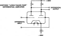
People who think that transistor amplifiers are zero output impedance (high damping factor) with perfect common-mode rejection of noise on the earth rail could learn a thing or two. Compromises are made at both the bass end, with electrolytic capacitor decoupling, and at the high frequencies for lots of reasons.
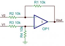
I practise, open loop gain falls dramatically at 20kHz, and for various reasons like stability and bandwidth limiting, the perfect input stage that rejects common-mode noise is rarely implemented correctly. For the theory to work, the components around the +ve and -ve inputs must be the same.
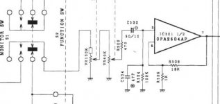
See that 47pF capacitor on the preamp stage to keep it stable. Why that's of the same order as the cable capacitance!
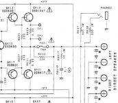
And look at those 0.22R resistors on the output stage. Again of the same order as the the cable resistance. It's only the feedback on the open loop gain that's holding it all together. The 10R and 0.1 uF Zobel at the output is to protect against open circuit condition, but will reduce the slew rate.
There are many reasons why amps sound good or bad. And they have some science behind them. So I'm not too quick to dismiss cable lifters. But there may be a better way to fix this.
How could a few hundred pFs of capacitance or a nH of inductance in a speaker cable affect things? Coaxial Line Calculator
Just to be thorough, I looked up GKF's particular cables:
Mogami GOLD SPEAKER SO-06 Speakon-Speakon Speaker Cable - 6' | Sweetwater.com
Pro-Audio stuff, Speakon connectors, but essentially a regular twin pair cable.
People who think that transistor amplifiers are zero output impedance (high damping factor) with perfect common-mode rejection of noise on the earth rail could learn a thing or two. Compromises are made at both the bass end, with electrolytic capacitor decoupling, and at the high frequencies for lots of reasons.
I practise, open loop gain falls dramatically at 20kHz, and for various reasons like stability and bandwidth limiting, the perfect input stage that rejects common-mode noise is rarely implemented correctly. For the theory to work, the components around the +ve and -ve inputs must be the same.
See that 47pF capacitor on the preamp stage to keep it stable. Why that's of the same order as the cable capacitance!
And look at those 0.22R resistors on the output stage. Again of the same order as the the cable resistance. It's only the feedback on the open loop gain that's holding it all together. The 10R and 0.1 uF Zobel at the output is to protect against open circuit condition, but will reduce the slew rate.
There are many reasons why amps sound good or bad. And they have some science behind them. So I'm not too quick to dismiss cable lifters. But there may be a better way to fix this.
Attachments
Last edited:
No-one accused you of being the village idiot, but you have demonstrated an inability to read or understand well accepted concepts of line impedance v frequency. My dad ( a POTS engineer) taught me this 55 years ago!
Your post above is a complete miss-mash of confused ideas and mis-understandings. Please go and study electronics.
I can't be a###d to attempt to explain - others have already tried.
Your post above is a complete miss-mash of confused ideas and mis-understandings. Please go and study electronics.
I can't be a###d to attempt to explain - others have already tried.
People who think that transistor amplifiers are zero output impedance (high damping factor) with perfect common-mode rejection of noise on the earth rail could learn a thing or two.
What people are those, specifically? How does that even vaguely pertain?
Apparently the authors (it's often interesting to click on the History and Talk tabs) decided it belongs in the article on transmission lines, where I found it by clicking and reading:That could be because the person who wrote the Wikipedia article assumed the reader had the knowledge to put the article into the proper context.
Transmission line - Wikipedia, the free encyclopedia
![That-Looks-Better2[1].jpg](/community/data/attachments/424/424160-f3b147845a404e62df4b47f4098a8df6.jpg?hash=87FHhFpATm)
- Status
- Not open for further replies.
- Home
- Member Areas
- The Lounge
- Speaker Cable lifters or stands?