how about this way of thermo-coupling?
(to 92 in "69" POSE 🙂 )
that one is good idea too yes 🙂
Regards
Juan
Hi Juan, an absolutely impressive layout. Looks great.
regards olaf
thank you sir 🙂
Regards
Juan
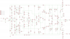
yes sir you got it 🙂 , maybe your part number are different from your software layout so don't fallow my simulation PDF so you don't get confuse, use original schematic 😉 and you be good to go
what I did is to simulate the circuit then I use the same part numbers from the simulation and use them as guide on the layout
Q3,Q4 are thermal twins
Q6,Q13 are thermal twins
Q14,Q11 are thermal twins
Q23,Q24 are thermal twins
when I mean twins is that they share the same temperature core for been together,
I was thinking to couple them with a little thermal paste then surround them with a small piece of shrinking tubing there is more theories about this but let go simple for now 😀
yours look amazing sir
yes you did it nice 🙂 now those 8 important TO-92 are placed correctly nice Idefixes
here is what mister Miles post a few days ago 🙂
really important sir, keep looking and fallow the layout and circuit as many time as you can so you be sure all is correct before your order a few, just today I saw a minor error on my layout and it does happen sometimes we don see it right away 🙂
Regards
Juan
Hi Juan,
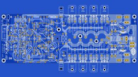
As there wasn't any part number (not value) on Miles schematic Eagle introduce them automatically. I just organize them : mostly symetrical part are numbered impair in -V area and pair for +V area then non symetrical left to rigth (Follow schematic under). I had to spend time on cheking layout but as eagle provide accurancy between schematic and layout with linking unrouted tracks issue can only come from schematic and issue in library model pin distribution.
Marc
Attachments
A33
Finaly finished to put together my A33. For 3 weeks I tried to remove a annoying hum.
I used a toroidal traf , and couldn't reduce the hum not to hear it next to speakers at minimum volume.
Last change was to replace toroidal traf with a regular one , section 15cm (square) and the hum disappeared. Now I can't hear it at minimum volume , next to a 90dB pair of speakers. At max volume , no imput, a little noise , but I never reach at that point. That (very) little noise(at max point) could be due to the preamp...
C21,22 from the last post (VAS transistors B-C), is needed to be put ?
I only set those 22pF from predrivers.
Now I have to set parts , inside the housing , in places.
Attachments
![IMG_20150312_091701[1].jpg](/community/data/attachments/419/419848-5bae9b62c7a66c74eb7d1b54b5a29c0b.jpg?hash=W66bYsembH)
Last edited:
Maybe it was in wrong position , or something I misstake there. Or just maybe something wrong whith that itemA 10VA EI trafo will exceed a 1KVA toroid in emitted EMF.
OS
I appreciate your work , and I submit that you are right.This is a particular situation. I post a photo of the first situatin..
Attachments
![IMG_20150312_112036[1].jpg](/community/data/attachments/420/420019-9f9b432c4db989e70a3d89aefb44d33d.jpg?hash=n5tDLE25ie)
![IMG_20150311_120535[1].jpg](/community/data/attachments/420/420047-9bebe1ed2a00d2e208d992f3ebaab964.jpg?hash=m-vh7SoA0u)
One , discrete with diodes , 3X3300uF/63V on each rail(9900uF+/9900uF-)must be something about wireing... did you use one or two bridge rectifiers?
I made another one , for two bridge rectifiers , for each channel. I intended to to use sepparate supply for each channel, but the hum keep me occupied.
have you measured AC voltage between secondary endings?
there was a case when a man connected two secondary windings in oposite directions so he had (in his case) 20Vac between gnd and each end of secondary winding,but between endings he had 0V instead 40V - because they "denied" each other. amplifier worked "somehow",but not as it should.
there was a case when a man connected two secondary windings in oposite directions so he had (in his case) 20Vac between gnd and each end of secondary winding,but between endings he had 0V instead 40V - because they "denied" each other. amplifier worked "somehow",but not as it should.
Maybe it was in wrong position , or something I misstake there. Or just maybe something wrong whith that item
I appreciate your work , and I submit that you are right.This is a particular situation. I post a photo of the first situatin..
I'll place a bet that he did not test the transformer + rectifier + smoothing capacitor wiring, in stages, by using the Mains Bulb Tester, BEFORE he starting assembling the amplifier and it's Chassis.must be something about wireing... did you use one or two bridge rectifiers?
That transformer toroidal plus rectifier bridge plus capacitors where used before in other project amp, and also used for final testing of A33 module separate on the table. No issue.
The secondary winding where delivering the same 33.4V~. No difference with no charge.
Sorry, I put traf back on table now, and press it with a hard surface, like in housing, and.... Secondary winding deliver difference of 2.7V,when it's pressed. A little buzz,... I think I have to rewind secondary.....
Last edited:
Hi Juan,
As there wasn't any part number (not value) on Miles schematic Eagle introduce them automatically. I just organize them : mostly symetrical part are numbered impair in -V area and pair for +V area then non symetrical left to rigth (Follow schematic under). I had to spend time on cheking layout but as eagle provide accurancy between schematic and layout with linking unrouted tracks issue can only come from schematic and issue in library model pin distribution.
Marc
that is a good thing about Eagle it keep rubber band connection Sprint Layout 6 does not have that option so is a lot more like "hand on placements" I see that you add slew power supply designs from OS slew main power board caps C12,C14C16,C18 positive rail and C11,C13,C15,C17 negative rail, I didn't think about that 🙄
Regards
Juan
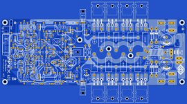
Hello guys I just want it to show you a "visual representation" on how is gonna look like with two popular transistor structures TO-3PL and TO3P I think looks great 🙂 the PCB size is about 277.5 mm x 100 mm for power transistors I'm gonna use MJL3281A/MJL1302A or maybe Sanken ok guys I will then take a break on this until I have the PCB and test it I will post results
wish me luck guys
soon I will order
"sorry I have to edit" soon in a few weeks 😛
Regards
Juan
wish me luck guys
soon I will order
"sorry I have to edit" soon in a few weeks 😛
Regards
Juan
Attachments
Last edited:
Can this amplifier run at +-50v?Don't use these 2n5401 transistors!
I see using here a970,amplifier is more musican.
In VAS stage i use ksa1381,ksc3503.
Pay attention for wrong pin placement only!
Can this amplifier run at +-50v?
You mean the A33 thimios ?
Regards
Juan
Attachments
Hi Juan,no i mean ax-14You mean the A33 thimios ?
Regards
Juan
Can this amplifier run at +-50v?
Yes, from +/-25V to +/-60V (+/-110V is maximum rail voltage with more outputs)
The AX14 only has one pair of outlets. I wouldn't go any higher than +-50v and even then I wouldn't run it on 4ohms.
Thanks Mile🙂Yes, from +/-25V to +/-60V (+/-110V is maximum rail voltage with more outputs)
- Home
- Amplifiers
- Solid State
- 100W Ultimate Fidelity Amplifier