watch out for an impedance curve for those speakers.Impedance is 8ohm
Coil inductance is 0.54mH
most of the time 8ohmers are more like 6ohmers.
but flattening the curve down to 8 ohm is still an improvement.
take care that the impedance is not dropping to much at the higher frequencies.
this can happen if values are not chosen carefully.
I can understand that if I am building the speakers from scratch myself, the Zobel is something that needed to be considered. Does one still need a Zobel if using commercially purchased speakers? I presume the designer would have built that in since they know the electrical characteristics of the speaker better than anyone else.
Regards,
Regards,
I can understand that if I am building the speakers from scratch myself, the Zobel is something that needed to be considered. Does one still need a Zobel if using commercially purchased speakers? I presume the designer would have built that in since they know the electrical characteristics of the speaker better than anyone else.
Regards,
Presumably yes. A zobel changes how a crossover filter works. If the crossover filter is optimized for a speaker without a zobel then adding one will significantly degrade the speaker performance.
However, I think the question here was more regarding how a class D amplifier and the output filter sensitivity to impedance changes affect the amplifiers performance. Therefore the question is relevant to even actively filtered speakers.
In some respects it is no different than what people have been doing for years by adding a series resistor on an actively filtered tweeter to "soften" is up a bit as many tweeters have extremely low Qts and if just actively filtered with no compensation will sound quite dull. Or adding a fairly large value series capacitor to an actively filtered tweeter to block all DC that may be present on the output of the amplifier. The latter is fairly commonly used with ultra high sensitivity compression drivers as they are sensitive to even a few mV of DC.
Last edited:
Presumably yes. A zobel changes how a crossover filter works. If the crossover filter is optimized for a speaker without a zobel then adding one will significantly degrade the speaker performance.
However, I think the question here was more regarding how a class D amplifier and the output filter sensitivity to impedance changes affect the amplifiers performance. Therefore the question is relevant to even actively filtered speakers.
In some respects it is no different than what people have been doing for years by adding a series resistor on an actively filtered tweeter to "soften" is up a bit as many tweeters have extremely low Qts and if just actively filtered with no compensation will sound quite dull. Or adding a fairly large value series capacitor to an actively filtered tweeter to block all DC that may be present on the output of the amplifier. The latter is fairly commonly used with ultra high sensitivity compression drivers as they are sensitive to even a few mV of DC.
Saturnus,
Thank you for the reply. I was not querying the discussion. Merely asking a question.
I have been trying to understand the interaction between the output filter of a class D amp and the crossover of the speakers for a while. Unfortunately, my very limited knowledge is no use to this complicated situation. You have one LC circuit (the output filter) connecting via a long cable to another complicated LC circuit (the crossover) which is connected to another inductor (the driver). I suspect the mechanical response of the driver's cone is also part of the interaction too

Regards,
For woofers/fullrangers, the Re+Le dominates the impedance except around resonance, and if your resonance is ~100Hz and your output filter crosses over well past 10K, it doesn't make a huge difference on the calculations. Tweeters might be a bit different.
I posted a bit of Matlab/Octave code in the 'rambling calculations' thread in this forum, wouldn't be too hard to expand the calculation of the speaker Z to include multiple drivers hanging off a crossover... see if you can find out the TS parameters of your speakers and a schematic for their crossover.
I posted a bit of Matlab/Octave code in the 'rambling calculations' thread in this forum, wouldn't be too hard to expand the calculation of the speaker Z to include multiple drivers hanging off a crossover... see if you can find out the TS parameters of your speakers and a schematic for their crossover.
For woofers/fullrangers, the Re+Le dominates the impedance except around resonance, and if your resonance is ~100Hz and your output filter crosses over well past 10K, it doesn't make a huge difference on the calculations. Tweeters might be a bit different.
I posted a bit of Matlab/Octave code in the 'rambling calculations' thread in this forum, wouldn't be too hard to expand the calculation of the speaker Z to include multiple drivers hanging off a crossover... see if you can find out the TS parameters of your speakers and a schematic for their crossover.
gmarsh,
Thanks! I am reading your link to Zobel, good education for people like me.
Regards,
Has anyone heard the finished Breeze Audio TPA3116D2 2.0 channel amp? How did you think it sounded, stock and what is the potential for easy (I'm lazy!) mods to it? 🙂
How about the Mo-gu F900 (supposedly uses the TPA3110 chip):

Don't care about the bluetooth function, but perhaps it has something like the Sure TPA3110 board in there? Anyone know? 🙂


I got it. It sound better than my Lepai.😀
This inbetween ground on cord and Astron should eliminate hum while retaining safety. It's made for this specific issue.
DENO-25-0001 Schurter | Mouser
I do not understand very clearly: is this meaning on the mains BEFORE the Astron or on the cord AFTER the Astron going to the board..? 🙄
That choke is intended to go in series with the AC ground.
Got it, thanks!
Nice! Have you ever opened it up to look at the parts inside
I got it. It sound better than my Lepai.😀
Separate regulated power supply for the AVCC pin.
Isolating of the AVCC power pin yielded great improvement IMHO. I use the 3.3 R and 10R resistors to decouple the power supply.
At the moment, I am using a LM 338 regulated linear power supply for the TPA 3116 and TPA 3123 boards.
Is it feasible to build another LM317 regulated power supply dedicated to the AVCC pin via another transformer ?
We can adjust the power supply to within 0.1 V for the PVCC and AVCC rails.
Is this idea feasible ??
looking forward to replies from more the knowledgeable .
thanks
kp93300
LM317 perhaps not the best choice because of the relatively low current draw from the AVCC supply. Better to use a shunt reg like TL431 and filter its output (because TL431's not the quietest of regs) with an LC. As you already have a higher voltage rail available from your present transformer - that is, what's feeding your LM338 input - you have no need for an additional trafo.
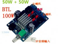
How do I wire up things to get that 100w mono?
You use a 24V supply and a nominal 3 ohm speaker.
Neither is recommended.
You use a 24V supply and a nominal 3 ohm speaker.
Neither is recommended.
This board shows up on the site as 50w + 50w capable, or mono 100w in a bridge mode.
There is some explanation on the Chinese site how to wire it up using + and _ outputs, but it makes no sense.... the explanation is very weird.
Trying to know if someone had bridged a board like this before, and what's the correct wiring.
Here's the wonderful explanation... if someone can make sense of this:
Support and linking bridge connection (PBTL) 100W mono output, speaker wiring: horn " + "then Lout ( + ) or ( - ), the speaker " - "then Rout ( + ) or ( - ), the other two pick imports blank.
What?????? Something got lost in translation somewhere! 😕😕😕
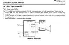
The information you seek is in the data sheet:
http://www.ti.com/lit/ds/symlink/tpa3116d2.pdf
The "50w + 50w capable, or mono 100w in a bridge mode" is quoted in many listings for this IC.
http://www.ti.com/lit/ds/symlink/tpa3116d2.pdf
The "50w + 50w capable, or mono 100w in a bridge mode" is quoted in many listings for this IC.
stereo 2x50w 24V/4ohm is already bridged, mono 100w 24V/2ohm is parallel bridged.
early in this thread some tested how chip performed with voltage, from 24V going down an clear improvement was found once getting below 21V, I doubt this is valid for all ampboards but it could be.
early in this thread some tested how chip performed with voltage, from 24V going down an clear improvement was found once getting below 21V, I doubt this is valid for all ampboards but it could be.
- Home
- Amplifiers
- Class D
- TPA3116D2 Amp