Hi there! I'm still casing the DCB1 🙁 But this time, I made a bad mistake. I'll try it better next tomorrow, but I'm quite concerned I could have burnt an IRFP2940.
Two questions: is there a method to test it's not totally gone, without applying current? Can I change it with another one, or it should be "paired"?
Thank again!
Marco
Two questions: is there a method to test it's not totally gone, without applying current? Can I change it with another one, or it should be "paired"?
Thank again!
Marco
No need to be paired in DCB1
http://www.diyaudio.com/forums/parts/90216-irf540-irf9540-can-these-tested-dmm.html
http://www.diyaudio.com/forums/parts/90216-irf540-irf9540-can-these-tested-dmm.html
Planning to use my DCB1 to feed my Fetzilla, where would you guys recommend i put my SMD Dact-style attenuator, before the DCB1 or between DCB1 and Fetzilla?
My sources are varied, Subbu DAC, iDevices, various other bits of kit.
Looking forward to testing both variations out myself.
My sources are varied, Subbu DAC, iDevices, various other bits of kit.
Looking forward to testing both variations out myself.
Before the DCB1, but after the source selector. If you are using one of the DCB1 pcb's just wire it where the volume pot would go.
Edit: oops, i forgot the Hypno board doesn't have a volume pot location. Still, I would suggest after source selector but before buffer.
Edit: oops, i forgot the Hypno board doesn't have a volume pot location. Still, I would suggest after source selector but before buffer.
Last edited:
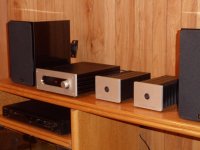
I just wanted to thank all of you who helped me complete this build. My DCB1 is completed and functioning well. I tried to post photos but was unable to do so as the web site required a "security token." Thanks once again to all of you.
You are welcome. You can upload photos than inserting them as links. There is "manage attachments" button underneath after you press "go advanced" answering button.
http://www.diyaudio.com/forums/attachment.php?attachmentid=469365&stc=1&d=1425395293
This is the only way I am able to upload a photo of DCB1 build. A problem with the site i think.
This is the only way I am able to upload a photo of DCB1 build. A problem with the site i think.
Attachments
http://www.diyaudio.com/forums/attachment.php?attachmentid=469366&stc=1&d=1425395493
Sorry for dual post and lousy photo.
Sorry for dual post and lousy photo.
Attachments
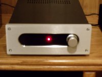
Why 10.45Megapixels, when 60kilopixels would have done?
Attachments
Last edited:
http://www.diyaudio.com/forums/attachment.php?attachmentid=469365&stc=1&d=1425395293
This is the only way I am able to upload a photo of DCB1 build. A problem with the site i think.
Very elegant looking set, congratulations for your builds. I hope you enjoy them musically too.🙂
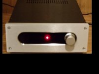
P.S. What was finally the culprit that gave trouble earlier? The 7812? Tx wiring for the PCB terminal?
The transformer was incorrectly wired. The IEC inlet required a fuse module that incorporated the proper jumpers. Without the proper jumpers the primaries could not be activated.
Last edited:

http://www.diyaudio.com/forums/attachment.php?attachmentid=469365&stc=1&d=1425395293
This is the only way I am able to upload a photo of DCB1 build. A problem with the site i think.
Nice setup mbain,
tried to look thru some older post but could not find any info regarding your nice enclosures,
Is the enclosures on the bench all the same brand ?
May i ask where you got them?,
am wondering about something like this for a slim BIII build.
The enclosure for the DCB1 is available via the DIY store. I bleed the face plate to my own specs (the longitudinal cut out). The design is similar to the Bel Canto products. The smaller amps are the "Amp Camp" kits, also available from the DIY store.
Hi folks! Just finished up my Hypnotize version of Salas' DCB1 (boards and kit from Tea Bag) and it looks like I've run into some problems. I wonder if fine folk here would mind holding my hand through some troubleshooting?
My problem -- or at least the symptom of my problem -- is the relay is not clicking on, so no output. Preliminary info:
- running a 50va 15v transformer (Triad VPT30-1670)
- relay is 12vcd (NEC EA2-12NJ)
- all LEDs are lit, status LED included
- V+ and V- to gnd show +9.8V and -9.8V respectively.
- I see about a .8-.9V drop across the CCS resistors (10ohm) - I am not exactly sure I am measuring this correctly. Basically looking at DC to gnd on each side of the resistor and subtracting (= drop)
- V to gnd on either side of the diode at the relay is about 9.8V again. (is this enough to turn on the relay?)
Where should I start investigating here? Please be gentle with me. I've built many kits, but my fundamentals still lack.
Thanks in advance!
EDIT: I have a sneaking suspicion this transformer is not putting out enough voltage. When I measure VAC on the power inlet to the board (after the transformer -- so I'm putting one probe on GND and the other on either lug of the power inlet) I am only seeing 10.1 - 10.3 VAC. Shouldn't it be 15? Could improperly paralleling the secondaries cause this? However, I just tried putting one probe on one side of the secondary and the other probe on the other (so one on + and one on - I guess) and got 17.05V, so assume this is the correct value. Back to square one.
Last edited:
- Home
- Source & Line
- Analog Line Level
- Salas hotrodded blue DCB1 build