An externally hosted image should be here but it was not working when we last tested it.
That's a pretty foolproof design!
Yes, a lot of thought (and testing/trial and error). I have been running my sub with the amp externally.
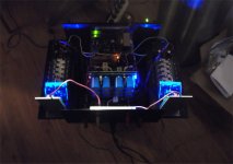
Down where the trafo goes (bottom), standing waves in the enclosure keep
vibration to a minimum. Near the top where the port is has unreal vibration.
I might wrap that poor little wolverine in foam neoprene (it is nearest to the top).
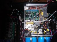
Control PCB (and relays) are down near the trafo (at the bottom).
OS
I've found a glue gun with the clear glue sticks works well. The clear glue stays a little softer and dampens vibration well. I glue any larger parts in place.
Party relays !!
Running 200W peaks makes these SS relays increase only 5C .... that's all.
Used an oral thermometer whilest cranking the snot out of the slewmasters. 😱
(below ) is my "hackjob" on the relay PCB's ... reduced foil makes very
little difference.
Tried the MJE340 thermals , needed to use an external heat source - can't
get the amps warm at all , even at 200W ! 🙂
I feel "safe" now to shake the house. I ran without relays for a while -
ABSOLUTELY no sound quality changes - SS relays are quite "transparent".
Audiophools who think 2 MOSFETS will "sour the sound" .... what a joke !
OS
Attachments
hi OS,
which mosfet did you use for ss relay?
Let me answer this one 😉
Infineon IPB025N10N3 G
Cheers,
Valery
thanks Valery.. out of stock in RS
I just use a potential divide before the PIC input pins.
I use one pin for positive going signal and another pin for negative going signals.
If the PIC sees DC for more than 500mS it turns off the relay.
is'nt it will damage the input with large negative voltage?
Valery, I'm having a bit of strange operation of the LED in my Slewmonster. I'm just looking over the original schematic for the LED. Is R1 supposed to go to ground or is it supposed to be a pull up resistor? My LED never quite shuts off.
Valery, I'm having a bit of strange operation of the LED in my Slewmonster. I'm just looking over the original schematic for the LED. Is R1 supposed to go to ground or is it supposed to be a pull up resistor? My LED never quite shuts off.
Hi Jeff, it's actually not expected to go off completely 🙂
Dimeed light indicates standby. As soon as soft-start sequence is initiated, the led goes a bit brighter. As soon at the amp is fully on and the speakera are connected, the led goes full brightness.
R1 goes to ground.
Hi Jeff, it's actually not expected to go off completely 🙂
Dimeed light indicates standby. As soon as soft-start sequence is initiated, the led goes a bit brighter. As soon at the amp is fully on and the speakera are connected, the led goes full brightness.
R1 goes to ground.
Okay. I've hooked a tiny LED up this time. It must just be brighter. I've never noticed it staying dim before.
Ah, ok - I've always used the small (3mm) ones - they seem to be more "sensitive" than the bigger ones.
I've got it fed from 12V on this board and am running an LED with a dropping resistor built in. I'll likely need to adjust resistors a bit to get the intensity corrected.
What , Jeff .... the script I sent you don't work ?
Val's indicator was alright , but my kids leave the amp on and
I just wanted a very verbose indicator of status. (where the LED will actually
turn off- or change color).
I had the same issue with the brightness contrast levels , a much higher value
R22 worked , but this also depends on the type/color (Vf) of LED.
OS
I haven't tried your script yet. I've just been trying to get my Slewmonster ready to test at home today but not having the best luck again.
Have you had any issues with thermal alarms? I'm getting some false triggering. It seems sensitive load or input signal.
Have you had any issues with thermal alarms? I'm getting some false triggering. It seems sensitive load or input signal.
I just had a mje340 out on leads to torch up with a bic lighter to test for operation.
I left the mje in circuit during operation (listening tests).
Absolutely no unexpected (false) triggering or other errata with this board. All 3
of these control boards are "right on". I do not compliment often , but these
are pro controllers.
I wish I was your neighbor 😀 ,
you most likely have a few small "housekeeping issues" with both the control board and slewmaster wiring.
Mine is 110% !!
I you posted VERY detailed photo's of all your wiring/layout , I'm sure me or
Val could spot one of these "housekeeping issues".
PS - I actually have my control board ground isolated from the chassis. I might
run one more 20ga green wire to my main chassis star - but .... Nothing is presently
wrong - should I bother ??
OS
I could use a hand with the housekeeping but I don't think I'd want a neighbour with a 250 watt Slewmonster.😀
Don't chassis ground your protection board. There would be no advantage to it and it would just bypass your ground loop breaker and chassis ground your audio ground.
I've got a little burn in time on the amp now. I'm going to take it apart and recheck VAS current and voltages. I'll take a couple pictures of my hook up while it's apart.

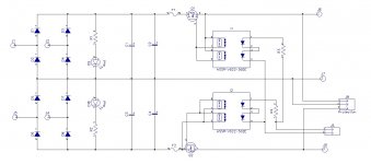
I've come up with a supply with rail disconnect mosfets to shut it down in case of a fault.
Will this take 100 volt rails and what is the max current?
Looks good too.
No bouncing relays here or on the output either...😀 PERFECT
Will this take 100 volt rails and what is the max current?
Looks good too.
No bouncing relays here or on the output either...😀 PERFECT
For 100V rails it will require adjustment of a couple of resistors in the DC offset sensor.
Relays will most likely be required in the main trafo AC circuit, providing its soft-start, unless we come-up with the relay-free solution for that as well 😉
Relay free solution is in the works. All the parts are waiting. Just need some time to breadboard.For 100V rails it will require adjustment of a couple of resistors in the DC offset sensor.
Relays will most likely be required in the main trafo AC circuit, providing its soft-start, unless we come-up with the relay-free solution for that as well 😉
- Home
- Amplifiers
- Solid State
- How to build a 21st century protection board