no thump sound and about the input cap
Hi all !
Thanks for all the kind replies in the previous discussions. I am now using the NI datasheet values for my Zobel. I think I will leave it like this until I have better tools to help me analyze what is really going on. 🙂
I'd like to share my experience on thump sound after the amp is shutdown.
I've built three of this amp, I notice one of my amp does not produce the "thump" sound after about 2 seconds shutdown. The others make this thump sound.
1. First built, point to point --> the thump is there
2. Second built --> pixel veroboard with a "ground bus" made by connecting the dots with soldering tin along the veroboard and all ground connections are made to this bus --> no thump
3. Third built --> pixel veroboard without a ground "bus bar" but all ground connection is made to a single point (or a "node" ?) --> the shutdown thump is there.
The same PSU and box and terminals apply to these amps.
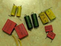
I also notice that the green cap (see the image) subjectively sounds better than the other caps.
Hi all !
Thanks for all the kind replies in the previous discussions. I am now using the NI datasheet values for my Zobel. I think I will leave it like this until I have better tools to help me analyze what is really going on. 🙂
I'd like to share my experience on thump sound after the amp is shutdown.
I've built three of this amp, I notice one of my amp does not produce the "thump" sound after about 2 seconds shutdown. The others make this thump sound.
1. First built, point to point --> the thump is there
2. Second built --> pixel veroboard with a "ground bus" made by connecting the dots with soldering tin along the veroboard and all ground connections are made to this bus --> no thump
3. Third built --> pixel veroboard without a ground "bus bar" but all ground connection is made to a single point (or a "node" ?) --> the shutdown thump is there.
The same PSU and box and terminals apply to these amps.
I also notice that the green cap (see the image) subjectively sounds better than the other caps.
Attachments
You need to see the stability section of the datasheet and add two more parts as indicated therein.Hi all! Thanks for all the kind replies in the previous discussions. I am now using the NI datasheet values for my Zobel. I think I will leave it like this until I have better tools to help me analyze what is really going on. 🙂
Choosing between 5 different models of most likely caps is the "5 peers" method of cap selection and very smart. Kudos!I also notice that the green cap (see the image) subjectively sounds better than the other caps.
The little green one has more opportunities in its construction, which is an indicator of what it *could* do not an certain indicator of what it will do. So, it is good that you tried it in competition with some likely peers.
It may also useful to try an ordinary little green polyester dip (not box) cap, likely range 4n7~22n as a bypass cap (parallel with a larger cap) so as to try for finer results. A wrong size bypass cap will affect the tone; but, a right-size bypass cap will make the imaging/soundstage and/or clarity much nicer without changing the tone. So that is a fairly small cap added in parallel with the larger cap.
Bypass cap is also applicable at the in- coupler, which is a bigger value and therefore a little more spectacular if a just-right size bypass cap is added to it.
Last edited:
volume control
Hi Daniel !
For volume control, I know you have once suggested me to put a potentiometer for a passive volume control or having an active preamplifier (due to variable impedance seen by the amp if a pot is used).
Just recently I read about shunt volume control as proposed by HarryHaller and drawn by planet10 at this post
The wiring connection is different from the "usual" passive volume control.
I am using this volume control with a resistor of 22k with 100k pot (at the moment these components are available with me).
What do you think of this "shunt" volume control? Any suggestion on the value of this resistor and pot specifically for LM1875?
Thanks.
In my opinion that is a waste of time.
Just use the audio taper vol pot alone and wired conventionally.
Just use the audio taper vol pot alone and wired conventionally.
Hi AndrewT,
Thanks for the reply. Do you think a 100k pot is okay for my amp? I notice the sound changes as I turn up the volume from my source. So for a loud volume, treble is there (may I say the sound is more open?). But low volume, less open. Less treble. My apology for possibly asking the already discussed question. If it has already been discussed, could someone direct me to the link?
My current configuration is no pot (I just removed the HH-style volume control), and connect to the headphone out from my laptop (or my media player, a Transcend MP860). When I increase the volume from my player, I get treble. But when I decrease the volume (both from my laptop or my MP860), less treble. This does not seem to affect the bass sound. What do you think of this?
For a +/- 16v rail voltage, is 22k/1k feedback/shunt resistor suitable or should I go for a lower gain or increase the voltage?
Thanks.
Last edited:
100k vol pots suit virtually all source equipment.
It's receiver equipment (and cables) that might not suit unbuffered 100k vol pots.
It's receiver equipment (and cables) that might not suit unbuffered 100k vol pots.
Hi AndrewT,
I'll probably swap the cable which connects my player to LM1875 with a shorter one.
And following your post here, if I understood correctly, my player output is 32 ohm (I assume as it easily drives my 32 ohm headphone), and my LM1875 input impedance is 22k (per datasheet).
Vol pot = 100k, Receiver Rin = 22k
Vol pot input impedance = 100k||22k i.e. 18.03k
Is this impedance seen by the receiver as its input impedance and the same value seen by my player as its output load?
And this leaves the cable as the possible source of different passband as the volume level increase or decrease. Or have I misunderstood?
Thanks.
Last edited:
An amp that can drive 32ohm headphone is very likely to have an output impedance <<32ohms.
But heaphone amplifiers often have an added resistor on the output to make them "more" compatible with a very wide range of headphone impedances.
This added resistor can be as high as 100r.
The output impedance of the headphone amplifier is the output impedance of the amplifier + the added output resistor (if fitted).
You can measure the output variations to confirm the output impedance.
The method is described in quite a few posts on the Forum.
Many will recommend that the output impedance to input impedance exceed 1:5 and I reckon you can go as high as 1:20 without detriment. I try for 1:20 in every build. But I rend to use Buffers for every Source that might be incapable of driving medium length cables.
An unbuffered 100k vol pot has a maximum output impedance of ~25k. using 1:5 as the minimum then you require an input impedance of 125k, not 22k !
If you replaced the 100k with a 10k vol pot then the minimum Rin becomes 12k5 and could be 25k or even 50k. Your 22k for Rin falls into the acceptable range.
This interpretation or the way you are describing it seems all mixed up.Is this impedance seen by the receiver as its input impedance and the same value seen by my player as its output load?
And this leaves the cable as the possible source of different passband as the volume level increase or decrease. Or have I misunderstood?
Thanks Andrew,
So if 20k pot is used, max impedance is 10k//10k, i.e. 5k. Applying the ratio 1:5, then the input impedance of my LM1875 should be >=25k.
For the cable, can I use capacitance meter to measure cable capacitance? What is the "normal" capacitance value of a cabel for this purpose?
And if I understand correctly a series resistance and shunt capacitance of a cable will form a LP Filter (CMIIW). But then my question, for this configuration (player - cable - pot - lm1875), this will form a kind of T-equivalent network of series resistance of cable then a shunt capacitance of a cable and then the series resistance from the vol pot. Does this still form a LP Filter as I read a LP Filter form by a resistor and a shunt cap?
Output impedance (assume simple non reactive resistance) and cable capacitance plus the RF attenuation built into the input of the receiver act as an RC filter.
A cable typically has 30pF to 300pF per metre.
3m cable + RF attenuation could add up to near 1nF of load capacitance in parallel to the receiver's input Rin.
When the output impedance of a 20k vol pot set to -6dB is around 5k, then 1nF of loading will create a filter with an F-3dB @ 1/{2PiRC} = 1/{2*3.14*5000*10^-9} ~ 32kHz
This will be audible, even to starting to get deaf Members like me.
If the RF attenuation were also set to 32kHz then the total roll off at 32kHz would be ~ 6dB and ~ -2dB @ 16kHz. You would hear this noticably with FM radio.
100k vol pots and long interconnects roll off a lot of treble information.
10k vol pots can manage much better.
Buffered vol pots where the Buffer ensures the source can drive the cable are best of all.
A source-to-load impedance ratio of 1:5 for amps sounds reasonable, but many BJT amplifiers will benefit from a very low source impedance, say below 5k. Opamps with their output stages biased in the uA range may benefit from having a 50k load impedance. This is somewhat of a conflict.
Having a volume pot drive an interconnect cable is a bad idea, it will be prone to RFI. Better to buffer the cable or put the pot right at the load.
Having a volume pot drive an interconnect cable is a bad idea, it will be prone to RFI. Better to buffer the cable or put the pot right at the load.
Shorter cable is better 🙂
Hi AndrewT,
Thanks a lot for sharing.
I am now using a shorter cable (less than 1 meter including internal wiring in the amp) and have temporarily removed the pot until I have the 10k pot.
But still, I'd like to seek more knowledge from you (as well as other respected members of this forum). Is it possible to change the Rin of my LM1875? Let's say from 22k to 50k or 47k. Should the gain resistors be replaced as well?
Thanks.
Hi AndrewT,
Thanks a lot for sharing.
...
100k vol pots and long interconnects roll off a lot of treble information.
10k vol pots can manage much better....
I am now using a shorter cable (less than 1 meter including internal wiring in the amp) and have temporarily removed the pot until I have the 10k pot.
But still, I'd like to seek more knowledge from you (as well as other respected members of this forum). Is it possible to change the Rin of my LM1875? Let's say from 22k to 50k or 47k. Should the gain resistors be replaced as well?
The pot is right in front of Cin of my LM1875 (about 10 cm away). I have no longer used the pot until I get a 10k one to experiment with. The problem was a long cable from my player to this pot. My player's output impedance is ~1R and it seems the band frequency of my amp is narrowed during low volume....
Having a volume pot drive an interconnect cable is a bad idea, it will be prone to RFI. Better to buffer the cable or put the pot right at the load.
Thanks.
Can you post a schematic with the components labeled and valued?............... Is it possible to change the Rin of my LM1875? Let's say from 22k to 50k or 47k. Should the gain resistors be replaced as well?..................
I can then describe what can be changed.
BTW,
I like the Dr Cherry feedback. Have you seen it?
The LM1875 datasheet schematic and my similar schematic, years ago at post #3, could use a 15k input load resistor (instead of the 22k input load). I found a comment on that and it had something to do with keeping the tone more level.
Swapping one resistor is worth a try.
Swapping one resistor is worth a try.
Thanks AndrewT. I'll upload the schematic later. It is similar to NS datasheet. About Dr Cherry's feedback, do you have the link at which post it is?Can you post a schematic with the components labeled and valued?
I can then describe what can be changed.
BTW,
I like the Dr Cherry feedback. Have you seen it?
Hi Daniel, I have read the post but could not find the reason why you changed 22k to 15k. Could you elaborate more on this?The LM1875 datasheet schematic and my similar schematic, years ago at post #3, could use a 15k input load resistor (instead of the 22k input load). I found a comment on that and it had something to do with keeping the tone more level.
Swapping one resistor is worth a try.
My previous experience, as discussed in this forum, I found the overall bandpass of my system changed as I increased or decreased the volume. The problem might be still there, but it is not audible considering the level of volume I play the music. Previously, it was "terrible". I can understand that because the existing Cin and Rin (per NS datasheet) form a HPF and the cable and pot and any shunt capacitance connected to the signal path form LPF.
I am not sure whether the output impedance of my player (headphone out) is constant or not. I suspect the output impedance varies as I increase/decrease the player's volume. If it is not constant, then it may also affetc the bandpass frequency.
AndrewT suggested to check this output impedance on this post. However, I have not found the posts on measurement method to confirm this, yet.
Thanks.
Last edited:
Did a search and could not find the Member's recent post where he adopted the Cherry feedback to correct the LF error. He commented that he liked what he saw.
There are a couple of posts, more than a year ago, that have links to the Dr Cherry article. Not nested feedback, which is very different.
There are a couple of posts, more than a year ago, that have links to the Dr Cherry article. Not nested feedback, which is very different.
Yes, that is the Dr Cherry feedback & extracts from the article.
The http://www.diyaudio.com/forums/chip-amps/www.linearaudio.nl/Miscellane...rry ndfl.pdf link seems to have died.
Anyone know how to use wayback to get a copy back into DIYaudio's file system?
you asked:
They are related.
The http://www.diyaudio.com/forums/chip-amps/www.linearaudio.nl/Miscellane...rry ndfl.pdf link seems to have died.
Anyone know how to use wayback to get a copy back into DIYaudio's file system?
you asked:
And I mentioned Dr Cherry.Is it possible to change the Rin of my LM1875? Let's say from 22k to 50k or 47k. Should the gain resistors be replaced as well?
They are related.
Last edited:
You need to go to www.archive.org and type in that URL.
However I tried it and that page has not been archived.
There are a lot of pages that are not archived or blocked that can't be accessed. But some pages are available. You need to try it out to see which ones. In fact if a calendar opens up and the latest date has no page to show , try all the older dates and sometimes something does come up.
But you can go to
http://linearaudio.nl/linearaudio.nl/index.php/my-library/miscellaneous-stuff
But there doesn't seem to be a paper by Cherry there ! Maybe one should ask Jan about it.
Last edited:
I think this is the one?
On Feedback, Feedforward and Error Correction
Or probably this one?
http://www.epanorama.net/sff/Audio/Circuits/Pre-Amps/60W NDFL Power Amplifier.pdf
On Feedback, Feedforward and Error Correction
Or probably this one?
http://www.epanorama.net/sff/Audio/Circuits/Pre-Amps/60W NDFL Power Amplifier.pdf
Last edited:
- Home
- Amplifiers
- Chip Amps
- Beginner's Gainclone, HiFi LM1875, The Amplifier Board