Here´s a quick way of determining the membrane´s fs.
With the membrane horisontal, measure the sag x and then
fs = square root of g/x, divided by 2*pi
If the membrane sags 1 mm, the fs is 15,8 Hz.
With the membrane horisontal, measure the sag x and then
fs = square root of g/x, divided by 2*pi
If the membrane sags 1 mm, the fs is 15,8 Hz.
And the winner is...
Made a membrane of 0,5 mm silicone rubber and the foam as voice coil former.
Ridiculous low SPL although I cannot hear any resonances.
Suspect also that Q is high as the motor is far too weak.
l will not bother measuring it's frequency response.
No point to continue with this project; my present three AE TD15H aside will rule.
To me it is difficult to if the layout is right,or not.
Have you tried with only one set of magnets?Not push pull.
Bernt
Have you tried with only one set of magnets?Not push pull.
Bernt
Without push-pull I get even lesser movement as expected.
Did a double-check on the layout as well, all works as designed.
There simply not enough resulting force to get the membrane moving to any greater extent.
I reckon the SPL for the push-pull to be in the low eighties if not even lower.
To match one TD15H, I need at least 94 dB to start with.
Did a double-check on the layout as well, all works as designed.
There simply not enough resulting force to get the membrane moving to any greater extent.
I reckon the SPL for the push-pull to be in the low eighties if not even lower.
To match one TD15H, I need at least 94 dB to start with.
Strange .
I have been wondering too.
This might be the answer:
If you use stronger magnets, you will increase efficency but loose bass. Increasing the field strenth will kill the high Q necessary for bass reproduction. A friend of mine built overkill Magneplanar drivers but was very surpriced by the lack of bass... Baffles were about 1.2 x 2 m.
From Full range speaker post 346
Bernt
You can build high effiency push-pull drivers for frequencies above circa 150-200 Hz.
Report Post
Strange .
I have been wondering too.
This might be the answer:
If you use stronger magnets, you will increase efficency but loose bass. Increasing the field strenth will kill the high Q necessary for bass reproduction. A friend of mine built overkill Magneplanar drivers but was very surpriced by the lack of bass... Baffles were about 1.2 x 2 m.
From Full range speaker post 346
Bernt
You can build high effiency push-pull drivers for frequencies above circa 150-200 Hz.
Report Post
I aimed for a low Q as I want motor control
 and not mass control
  for bass reproduction.
But otherwise I agree.
Bass is best reproduced with traditional cone speakers and my AE TD15H is probably best in class.
At least for EQ:ed actively driven OBs such as mine where low Q and large Xmax is essential to get a tight bass down to at least 20 Hz.
I am rebuilding all my designs again using pictures for the diaphragm, if I don't have picture I use picture paper which is white and shiny. The aluminium tape is on the inside. I use 5 mm tape with the 18 mm ferrite magnets, and 6 mm tape with the 22 and 25 mm ferrite magnets. I use 3 mm tape with my neos of 12.7 mm width, all touching no gaps. Not worth the trouble of glueing I use double sided tape to fix diaphragm using a roller to control placement. I have also placed diaphragm without the double sided tape as it is held in position using picture frame wood.
Attachments


Just a few of my latest designs using pictures, mostly 60 x 40 mm, and some 4' x 2'. Using picture frames to hold in place. Very happy with the results. EASIER TO BUILD!
Interesting.
Can you post some frequency response and distortion levels curves?
What´s the SPL at 1 meter/1 Watt anyway?
Can you post some frequency response and distortion levels curves?
What´s the SPL at 1 meter/1 Watt anyway?
No, sorry don't have any measuring equipment, only my ears. But they compare very well with other speakers I have, including Quad Esl 57 and 63's, and Magnapan.
Then it's ALL imaginary.
If you say so, I'll just enjoy them in my imagination!, and keep living in my dream world!
But if you want someone to follow your design, and I guess that's why you post this, you must also post some measurements.If you say so, I'll just enjoy them in my imagination!, and keep living in my dream world!
Otherwise it'll be a wild goose chase for any follower.
MY LATEST REBUILDS
The large one uses ferrites the next 2 my little monsters use 50 x 12.7 x 3 mm neos, as I have said I don't use mylar or polyethylene any more. Quite happy with results no more funny noises caused by the noisy mylar!
The large one uses ferrites the next 2 my little monsters use 50 x 12.7 x 3 mm neos, as I have said I don't use mylar or polyethylene any more. Quite happy with results no more funny noises caused by the noisy mylar!
Attachments


The ultimate test of any design is what it sounds like, nothing else matters, as they say the proof is in the eating of the pudding, and my pudding tastes wonderful, and is easy to bake as well!
I am not interested in anyone following my designs, just trying to help you build a simple light design that works. This as been my goal over the last 15 years. I think I have finally reached that goal, after many years of trial and error!But if you want someone to follow your design, and I guess that's why you post this, you must also post some measurements.
Otherwise it'll be a wild goose chase for any follower.
Well @Jamesbos (Henry),
you might consider were a message like "please don't follow me" may lead to:
https://www.youtube.com/watch?v=Zjz16xjeBAA
🙂 😀
you might consider were a message like "please don't follow me" may lead to:
https://www.youtube.com/watch?v=Zjz16xjeBAA
🙂 😀
Last edited:
As I suspect that an English pudding is way too sweet for my taste buds, I still want some measurements of your design.The ultimate test of any design is what it sounds like, nothing else matters, as they say the proof is in the eating of the pudding, and my pudding tastes wonderful, and is easy to bake as well!
It is the only way that we can use in order to know if it is worth while to follow any of your designs.
Hi gentlemen,
dear friends of "the unusual concepts",
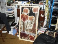
maybe this can be useful just as a "remark" or "alternative approach" in some respect, it is an "edge driven planar" i did 2009.
Just some pictures for your edififation. Fs in that cabinet was about 40Hz, lower (-3 dB) cutoff frequency around 50Hz. I was measuring at higher frequencies only, because this was intended to be a wideband system. But it works very well as a "low to lower mid" frequency transducer in the size given.
I was using a rather "special" software and not a good microphone at that time, sorry for that ... but should be sufficient to get an idea.
heee i missed that one, Linearray do you ahve mor pictures or discription on how this works ? looks like its driven from both left and right? by 2 coloms of sandwich magnets between steel ? a bit like the single colom of a rubanoid ?
im really curious. since i played allot with the rubanoids and might declare it dead and not suitable for mid/high frequencys as well 🙂 so moved on to amt's, but if this works well for the low end im pretty curious how it works
- Status
- Not open for further replies.
- Home
- Loudspeakers
- Planars & Exotics
- Yet another DIY Planar Bass