Living on the edge
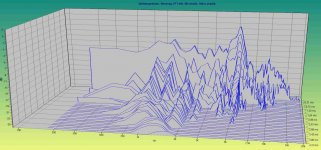
So should the fringe field be used or not? The field on the edge is not as linear and not as strong as the "middle field".
My current approach though is that it is better to use it than not; it will be a softer transition from the driven part of the membrane to the parts that are the passive surround.


A 6 mm wide aluminium foil would thus have this field variation on the edge at zero excursion (the middle line to the left):

This at 6 mm excursion (the lower/higher line to the left):

In the middle, linear part, there is this field at zero excursion (the middle line to the right):

And this at 6 mm excursion (the lower/higher line to the right):

So should the fringe field be used or not? The field on the edge is not as linear and not as strong as the "middle field".
My current approach though is that it is better to use it than not; it will be a softer transition from the driven part of the membrane to the parts that are the passive surround.
A 6 mm wide aluminium foil would thus have this field variation on the edge at zero excursion (the middle line to the left):
This at 6 mm excursion (the lower/higher line to the left):
In the middle, linear part, there is this field at zero excursion (the middle line to the right):
And this at 6 mm excursion (the lower/higher line to the right):
Last edited:
Having a narrower foil on the fringe part compensates for the weaker field.
That will be 0,20/0,30, that is 4 mm wide.
Struggling with Silhouette Studio Designer right now while waiting for , I mean
  .
.
That will be 0,20/0,30, that is 4 mm wide.
Struggling with Silhouette Studio Designer right now while waiting for
, I mean .Hi gentlemen,
dear friends of "the unusual concepts",
maybe this can be useful just as a "remark" or "alternative approach" in some respect, it is an "edge driven planar" i did 2009.
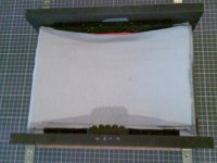
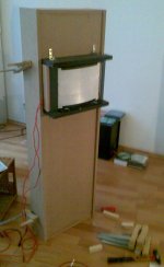
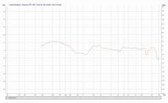
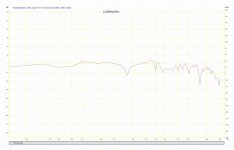
Just some pictures for your edififation. Fs in that cabinet was about 40Hz, lower (-3 dB) cutoff frequency around 50Hz. I was measuring at higher frequencies only, because this was intended to be a wideband system. But it works very well as a "low to lower mid" frequency transducer in the size given.
I was using a rather "special" software and not a good microphone at that time, sorry for that ... but should be sufficient to get an idea.
dear friends of "the unusual concepts",
maybe this can be useful just as a "remark" or "alternative approach" in some respect, it is an "edge driven planar" i did 2009.
Just some pictures for your edififation. Fs in that cabinet was about 40Hz, lower (-3 dB) cutoff frequency around 50Hz. I was measuring at higher frequencies only, because this was intended to be a wideband system. But it works very well as a "low to lower mid" frequency transducer in the size given.
I was using a rather "special" software and not a good microphone at that time, sorry for that ... but should be sufficient to get an idea.
Attachments
-
 02_Membranmaterial.jpg27.5 KB · Views: 248
 -
 04_Bild023.jpg315.4 KB · Views: 275
 -
 06_Bild042.jpg346.9 KB · Views: 297
 -
 10_Bild072.jpg382.2 KB · Views: 308
 -
 12_Bild071.jpg318 KB · Views: 273
 -
 13_Bild050.jpg123.2 KB · Views: 306
 -
 14_AL_BendingTransducer_OhneGehäuseFreistehend_Abstand_50cm.JPG262.3 KB · Views: 327
 -
 16_AL_BendingTransducer_ImGehäuseMitRaumanteil_Abstand_100cm.JPG185.7 KB · Views: 241
 -
 BendngTransducerZerfallsspektrum.jpg282.5 KB · Views: 229
Last edited:
I later decided to follow a (very) different approach in membrane structure and motor design. So this one has still a "place of charity" at the attic.
It was one of many steps towards a "fullrange bending wave loudspeaker", that i have designed and built some years later.
This particular design had significant "peculiarities" (not to say "problems" 😉 ) in the mid- and high range, but would be fully functional as a woofer.
With limited upper frequency of "quasi pistonic motion" (lowest bending mode used as a "forced motion"), this design could be made very large in size if necessary.
Last edited:
I would think using the fringe would only affect the polar response higher up. My monsoon push pull planars are built this way.
First full scale working membrane
Out of the Silhouette

came one third of one side of the coil:

Out of the Silhouette
came one third of one side of the coil:
Using the old 74 tape:

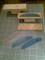
The first membrane frame was made of steel; it proved to be hard to get it into the structure even with some helper boards.


So I made the frame of aluminium instead (25x3 mm):

Attached three of these coils onto one side of the membrane, had to help the 74 film with some 77 glue especially where the aluminium strips where having so glue from the film:

The first membrane frame was made of steel; it proved to be hard to get it into the structure even with some helper boards.
So I made the frame of aluminium instead (25x3 mm):
Attached three of these coils onto one side of the membrane, had to help the 74 film with some 77 glue especially where the aluminium strips where having so glue from the film:
For the other side I adjusted the pattern a little to cover 6 columns instead of 4:

74-film:

On to the membrane:


74-film:
On to the membrane:
After that I ironed membrane to get the 74-film more even:

That actually proved to be a mistake; the grid didn't align to the magnets as well on the perimeter anymore as the 74-film also shrunk the membrane. The foil is still in the correct field though.
As a side effect, the actual membrane really stiffened.
That actually proved to be a mistake; the grid didn't align to the magnets as well on the perimeter anymore as the 74-film also shrunk the membrane. The foil is still in the correct field though.
As a side effect, the actual membrane really stiffened.
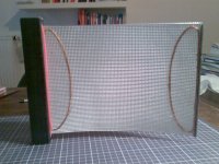
Time to put the membrane in the gap.
Put gaskets on both sides, that ought to align the frame in the middle of the gap:

Put a different kind of gasket on the frame where the frame were screwed together using a L-shaped support:

Put everything together:

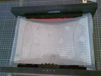
Now it was time for some tests...
Put gaskets on both sides, that ought to align the frame in the middle of the gap:
Put a different kind of gasket on the frame where the frame were screwed together using a L-shaped support:
Put everything together:
Now it was time for some tests...
Apart from a small buzz from some not so tight membrane in the lower left corner, which was easily fixed, no buzz came from the frame nor the structure.
So all was well then?
NO!
SPL was too low, at least 10 dB lower than my present setup.
Athough the membrane was moving to a fro a lot at 20 Hz, there were no audible output.
Perhaps some cancellation then but I had already extended the baffle by some 30 cm.
Resonances everywhere: at 60, 85, 90, 107, 120 Hz and so on.
It couldn´t be the room, these frequencies doesn´t show when I listen no my ordinary setup.
Also, each resonant frequencies also showed high distortion levels. And there were not even.
Even worse was the high Q-levels, when rapidly disconnecting the speakers it sounded a couple of seconds.
Of course, this membrane was a lost cause from the beginning: When I first mounted it on to the frame and "plucked" it, it sounded with the same boing as I now hear when I disconnect it. Also, it is at those frequencies I get the high distortion levels and resonances.
So I hadn´t made a loudspeaker, I made a music instrument!
Next membrane to test will be made of thin silicon.
Tried to find it in the manual or on their site. But no luck.Whats the accuracy on that cutter, and how wide a sheet?
Thanks Al
I guess it in the end depends on the material that you are cutting anyway
What´s your intended use? I can make a test cut if you want to.
PM/mail me some test design where the crucial parts are be tested.
Too complicated for a start, if you look at all my designs you will see they are a lot simpler, perforated sheet magnets diaphragm on thicker polyethylene using 3 mm aluminium tape using the epsilon style layout, no crossover required. No resistors for impedance, which relies on the size for total impedance, say from 6 ohms to over 12. My most popular size 60 x 40 cm weight 5 kilos. Using 50 x 12.7 x 3 mm neos. You can leave them uncovered or you can use material or a canvas frame. I have also used a print in a picture frame as the diaphragm, you can use any picture to keep the wife or partner happy.I wish all the best with your design, as I have been designing redesigning and building re-building for the last 10 years,as I have no knowledge of measuring results only by ear so I have learned from my mistakes, although I am not very organised, so it has kept me busy during my retirement, so all the best, keep rebuilding.
If we only concentrate on the bare membrane/diaphragm as the one I made have its own intrinsic resonances regardless of coil material or pattern and magnetic structure.
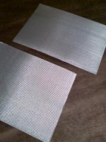
The Icarex weighs 25 gram per square meter, the membrane above is then a mere 14 grams.
You would then advocate a heavier diaphragm: "perforated sheet magnets diaphragm on thicker polyethylene"?
Another thing is the suspension/surround part of the membrane. In my case it consists of the same material, a 100 mm perimeter outside the active area.
Perhaps the surround should be made of another material?
If you are still using steel bars for your magnet support, I would use steel bars the same width as the magnets, makes a safer arrangement if you drop or knock the finished article as neos are quite good at jumping. As I found out to my cost before, twice.! Hell of a job to separate. I would instead of using 2 diaphragms only use one and put the other neos with the others, probably why it is insensitive. I have tried myself using the 2 diaphragm method not really worth the effort!! I always use my neos touching easier and more sensitive
- Status
- Not open for further replies.
- Home
- Loudspeakers
- Planars & Exotics
- Yet another DIY Planar Bass