Hi all , i need from STAX DA-80 or 80M schematic.
Walter
Hello,
I have only that DA100M 🙂
@ + JF
Attachments
Hi all , i need from STAX DA-80 or 80M schematic.
Walter
It's lucky day
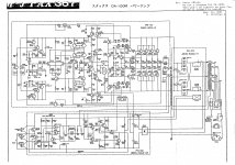
http://elektrotanya.com/stax_da80.pdf/download.html
@ + JF
Last edited:
hi, i have a pair of STAX DA50 , the output transistor are toshiba 2SC2565 and 2SA1095 don't know if they are the originals but it works . my question is there is a first trimmer wh seems to adjust the offset ( i adjust it to have 0V on the output ) ans there is a second one surely for the bias . what is the original bias for this amp ?
and the sound is refined but it lacks some bass even with my horn speaker do i need to change 30 years two power supply Caps ?
🙂
and the sound is refined but it lacks some bass even with my horn speaker do i need to change 30 years two power supply Caps ?
🙂
Unlike a lot of other power amps of that era, the Stax monaurals are full class A biased to peak output power (in 8 ohm).
100W peak output is ~3.6A, 0.9A per power device.
Makes about 425mV across each of the 0R47 white blocks.
(In the class AB setting, the 12.5W is peak class A. Better to adjust the quiescent current level with the amp switched to Full Class A)
If the amps still work, the A1095/C2565 can only be original Toshiba
thanks jack , any idea to upgrade parts or design ? caps , restore , output coil , Zobel filter, etc..
i like to play with danger 🙂
i like to play with danger 🙂
first step i have removed the output coil and replace it with a 0.1R resistor.
and let the ZObel filter .. works fine 🙂
and let the ZObel filter .. works fine 🙂
I'd exchange the feedback resistors for higher power versions, same value.
Renew all electrolytic caps, including the little ones.
- refresh the thermal paste between the aluminum mounting block and the heat pipe
- swap out the mica insulators for Kerafol ones.
- replace the 0R47 emitter resistors by matched ones (e.g. low inductance ones as MPC78)
In the power supply, I'd go for CRC/CLC. Either replace the old cans by new ones of half the original value or add some uF's.
Place snubbers on the bridge rectifiers (possibly an exchange by soft recovery diodes)
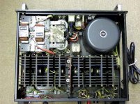
You have pictures of the insides of your amps ?
(pas des images, alors, ça c'est un crime très grave)
Renew all electrolytic caps, including the little ones.
- refresh the thermal paste between the aluminum mounting block and the heat pipe
- swap out the mica insulators for Kerafol ones.
- replace the 0R47 emitter resistors by matched ones (e.g. low inductance ones as MPC78)
In the power supply, I'd go for CRC/CLC. Either replace the old cans by new ones of half the original value or add some uF's.
Place snubbers on the bridge rectifiers (possibly an exchange by soft recovery diodes)
You have pictures of the insides of your amps ?
(pas des images, alors, ça c'est un crime très grave)

jacco you ruin me, i have ordered shootky diodes, 22000uf nichicon power supply , small ones nichicon FG , 0.47R non inductive emmiter resistor , kerafol insulator . i will report the result in a week or so ( if it will not burn before 🙂)
hi, i have a pair of STAX DA50 , the output transistor are toshiba 2SC2565 and 2SA1095 don't know if they are the originals but it works . my question is there is a first trimmer wh seems to adjust the offset ( i adjust it to have 0V on the output ) ans there is a second one surely for the bias . what is the original bias for this amp ?
and the sound is refined but it lacks some bass even with my horn speaker do i need to change 30 years two power supply Caps ?
🙂
Hello,
Yes, these are the original transistors. For Black for NPN and PNP for Green. This is the first evidence of originality.
No foolishness ... eh ... Because it is virtually untraceable.
I have seen many repaired with Sanken transistors
Yes, preferably, put much more uF. 30 years is a long time, and capacitors are doing, the recovery power filtering and Di / Dt Audio ... In the grave they are rinsed long time. (worn)
Ok for fast recovery diodes
50W Class A / 8 ohm load = 1,77A quiescent current 0,885A power per device.
If necessary, touch French private message. For technical information see also looked at the page of Jean-Marc Plantefève
2A & DIY
@ + JF
Last edited:
one amp upgraded , 3 hours of work , al caps new , shottky diodes, emiters resistors , coil removed , tuning on and damn it works 😀
tomorrow i 'll make the second one and will see if it"s a real upgrade or just for fun 🙂
anyway thanks all for your help..
tomorrow i 'll make the second one and will see if it"s a real upgrade or just for fun 🙂
anyway thanks all for your help..
Hi Guys
Why would you replace the output coil with a 100mR resistor? This just throws away power and ruins damping factor.
Someone complained about a lack of bass - was it with this amp? Changing the choke to a resistor will make the bass problem worse, as well, unless the point is to make an amp that has "soft" bass like a tube amp. That adds THD in the low mids and can give an impression of "more bass" but it is inaccurate bass and now inaccurate mids.
Self explains this in APAD as others have many times during the previous decades.
Have fun
ok , so i have removed the 0.1R resitor too .. both amp are now re-cap and work fine . the sounds doesn't change too much for the moment ( which is a good sign 😀)
now i have two amps to compare a brand new IRONAMP from michael design ( ok with 70's VFET ) and the 1980 STAX .. funny times 🙂
now i have two amps to compare a brand new IRONAMP from michael design ( ok with 70's VFET ) and the 1980 STAX .. funny times 🙂
Last edited:
Hello everyone The DA100 power supply circuit has diodes D301, 302 marked T3. Please tell me the modern analogue of these diodes. Thanks.ok , so i have removed the 0.1R resitor too .. both amp are now re-cap and work fine . the sounds doesn't change too much for the moment ( which is a good sign 😀)
now i have two amps to compare a brand new IRONAMP from michael design ( ok with 70's VFET ) and the 1980 STAX .. funny times 🙂
- Home
- Amplifiers
- Solid State
- Stax DA100 Link For Download The Schematic