Has anyone had experience with these particular ESLs
Mini Panels ?
I'm thinking about using them with a pair of
http://www.greatplainsaudio.com/downloads/416-8B Spec Sheet.pdf
in 3 cu ft (interior) sealed cabinets. The sealed boxes would limit the 416's low end
to 70Hz. That would likely help limit IM distortion, while they also handle up to around 700Hz. Below 70Hz, a pair of subs would take over. And I would bi-amp the 505s with the Altecs.
There's lots of good words about the 416 here; check out this thread
http://www.diyaudio.com/forums/multi-way/100392-beyond-ariel-781.html
and http://www.diyaudio.com/forums/multi-way/100392-beyond-ariel-1165.html ).
But has anyone ever built something with the 505 ESLs?
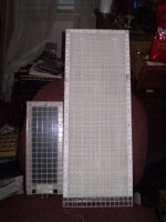
I haven't any experience with that particular panel but the size is nearly the same size of panels that I have made for my very first set.
I get the same performance out of my 4.5" x 10" panels (3.25" x 9.75" diaphragm size).
They mate very nicely with my Radio Shack Optimus PRO-CSW800 8" subwoofers!!!
I think that this size is an excellent combination and will give you great sound without being overly large.
FWIW
jer 🙂
I get the same performance out of my 4.5" x 10" panels (3.25" x 9.75" diaphragm size).
They mate very nicely with my Radio Shack Optimus PRO-CSW800 8" subwoofers!!!
I think that this size is an excellent combination and will give you great sound without being overly large.
FWIW
jer 🙂
Thanks jer. One concern I have is required power. Even though I'd be biamping the ESLs and the 416s, the amp for the ESLs will be a low power amp; only 25 wpc/8 ohms, 13 wpc/4 ohms. The specs on the 505s say 8 ohms, but no actual impedance curve is provided (though ER Audio said that it, as well as dispersion curves, are in the works). My room is relatively small, and ER Audio claims the 505s have 88db sensitivity. Since you said that your panels are about the same size, if they are also close to 88db sensitivity, what wpc did you need to drive them when listening about 3 meters away?
Last edited:
Here is a Quote of the description I did at ESLDIY as the data was still fresh in my memory at the time I was testing the system.
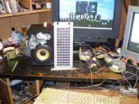
"The diagphram size of the desktop system is 3.25"x 9.75" using a 5.25" woofer.
This system will do more than 100db and has been measured in excess of 105db at 1 meter.
The large ripples in the Frequency Response chart are from reflections of the desk and monitors as shown in the test setup as I have eliminated these in other similar test setups.
As tested this setup used a 1:250 transformation ratio and about 4.5kv to 7kv of bias with only a 5v to 10v peak signal feeding the step-up transformer."
Using a 6.8KV bias and about 1:160 step-up ratio I was getting about 95db with just a 10Vpeak signal.
jer 🙂
A 5Vpeak signal is close enough but slightly more to the equivalent of 2.83Vrms or 4Vpeak.
At this level I got an average of 88db to 90db with 91db for a few peaks but I consider 89db about the average.
This works out as confirmed by my measurements of 6db more for every doubling of the drive voltage(and bias voltage for that matter).
My FR graph was set with 10Vpeak and at 95db.
I do my ESL voltage measurements in Peak voltage and not RMS because I like to know the peak voltage in case of any HV breakdown of the Stator coatings.
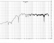
The last four graphs are the most accurate and calibrated graphs I have of the system in the First picture once I got it all setup and tuned in at 95db.
jer 🙂
"The diagphram size of the desktop system is 3.25"x 9.75" using a 5.25" woofer.
This system will do more than 100db and has been measured in excess of 105db at 1 meter.
The large ripples in the Frequency Response chart are from reflections of the desk and monitors as shown in the test setup as I have eliminated these in other similar test setups.
As tested this setup used a 1:250 transformation ratio and about 4.5kv to 7kv of bias with only a 5v to 10v peak signal feeding the step-up transformer."
Using a 6.8KV bias and about 1:160 step-up ratio I was getting about 95db with just a 10Vpeak signal.
jer 🙂
A 5Vpeak signal is close enough but slightly more to the equivalent of 2.83Vrms or 4Vpeak.
At this level I got an average of 88db to 90db with 91db for a few peaks but I consider 89db about the average.
This works out as confirmed by my measurements of 6db more for every doubling of the drive voltage(and bias voltage for that matter).
My FR graph was set with 10Vpeak and at 95db.
I do my ESL voltage measurements in Peak voltage and not RMS because I like to know the peak voltage in case of any HV breakdown of the Stator coatings.
The last four graphs are the most accurate and calibrated graphs I have of the system in the First picture once I got it all setup and tuned in at 95db.
jer 🙂
Attachments

Last edited:
Nice to see that they started selling the new panel (which should be better than the previous one). I've considered ordering a pair so I'm very interested in any measurements and subjective opinions about them. The only reviews I've found about the old panels is a thread on AudioCircle and this blog post.
I currently have a pair of OB woofer towers (2x4 Dayton Audio RS180-4) which should mate well with the mini panels.
I currently have a pair of OB woofer towers (2x4 Dayton Audio RS180-4) which should mate well with the mini panels.
Forgive my ignorance but what is the value of “smoothing” the FR when evaluating system performance? Is it to let you see the overall quality of the performance without “sweating the small stuff”, so to speak? And what software did you use to transform the “raw” response curve into the two or three smoothed ones that you show here?My FR graph was set with 10Vpeak and at 95db.
I do my ESL voltage measurements in Peak voltage and not RMS because I like to know the peak voltage in case of any HV breakdown of the Stator coatings.
The last four graphs are the most accurate and calibrated graphs I have of the system in the First picture once I got it all setup and tuned in at 95db.
jer 🙂
Within about 5db, can you estimate the FR of the larger ESL, minus the woofer?
Yes, You are correct.
Those graphs were done with REW and the db scale was calibrated to my SPL meter at 1Khz.
HOLMImpluse has smoothing as well.
I use both programs.
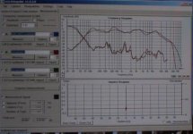
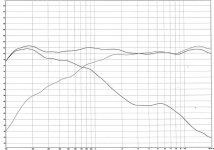
The First graph shows the response of just the woofer and just the ESL as well as both of them combined operating as one with three separate sweep tests.
That was an earlier measurement and shows some room reflections.
A larger ESL should have basically the same response as an ESL is naturally flat when measured in the Nearfield range.
All of my measurements were at 1 meter with the setup as shown on my desk.
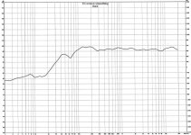
In the RAW chart the dips and peaks are caused from reflection's of the surrounding surfaces.
In the last 3 graphs I did use a blanket to help dampen some of these reflections as well (not shown in the picture).
I used Dayton EMM6 measurement microphone for these charts in 2012/13 (winter).
Back in 2010 I had done a similar measurement's using my Peavey TN520 microphone and surrounded my whole room with blankets to absorb the reflections and it too came out ruler flat for the very same panel at a foot to approximately 1 meter.
I was using Audacity at the time (2010) and I think those pictures are somewhere in this forum as well.
All of my measurements were very consistent even with using a few different microphones that I have, But the EMM6 is the flattest one I have and also comes with a calibration chart.
The low end drop off from dipole cancellation is calculated from the front to back distance of the panel (or where the width of the panel equals on half wavelength).
Adding wings increases this distance helps this by lowering the point of frequency were the response begins to drop due to Dipole Cancellation.
The physical width of the diaphragm itself will determine how much of a Beaming effect at the higher frequency's the panel will present.
If the width of the panel is increased as mentioned earlier by a thicker frame and/or adding wings this has no effect on the beaming qualities and only effects the point of the start of the low end dipole cancellation.
These two factors are not to be confused with one another as they are both completely separate functions of the system as a whole.
jer 🙂
Those graphs were done with REW and the db scale was calibrated to my SPL meter at 1Khz.
HOLMImpluse has smoothing as well.
I use both programs.
The First graph shows the response of just the woofer and just the ESL as well as both of them combined operating as one with three separate sweep tests.
That was an earlier measurement and shows some room reflections.
A larger ESL should have basically the same response as an ESL is naturally flat when measured in the Nearfield range.
All of my measurements were at 1 meter with the setup as shown on my desk.
In the RAW chart the dips and peaks are caused from reflection's of the surrounding surfaces.
In the last 3 graphs I did use a blanket to help dampen some of these reflections as well (not shown in the picture).
I used Dayton EMM6 measurement microphone for these charts in 2012/13 (winter).
Back in 2010 I had done a similar measurement's using my Peavey TN520 microphone and surrounded my whole room with blankets to absorb the reflections and it too came out ruler flat for the very same panel at a foot to approximately 1 meter.
I was using Audacity at the time (2010) and I think those pictures are somewhere in this forum as well.
All of my measurements were very consistent even with using a few different microphones that I have, But the EMM6 is the flattest one I have and also comes with a calibration chart.
The low end drop off from dipole cancellation is calculated from the front to back distance of the panel (or where the width of the panel equals on half wavelength).
Adding wings increases this distance helps this by lowering the point of frequency were the response begins to drop due to Dipole Cancellation.
The physical width of the diaphragm itself will determine how much of a Beaming effect at the higher frequency's the panel will present.
If the width of the panel is increased as mentioned earlier by a thicker frame and/or adding wings this has no effect on the beaming qualities and only effects the point of the start of the low end dipole cancellation.
These two factors are not to be confused with one another as they are both completely separate functions of the system as a whole.
jer 🙂
Bi-amped ESL/Altec 416 & Subs
A solution to reduce beaming at high frequencies from small ESL panels, is claimed by use of an acoustic lens in SoundLab’s MiniStat. The MiniStat uses two 5” x 5” ESL panels fitted with these lenses which are said to expand dispersion to 90 degrees. SOUND LAB
With the hardware choices of my bi-amped ESL/Altec 416 midwoofer/sub system now complete, I am set for my first learning experience with testing and alignment software.
Thanks for the mic recommendations. That Dayton EMM-6 is certainly affordable and popular with a lot of users.
I had never heard of REW until now. I just had time today to glance at the website; I noticed the dedicated button that might make doing response overlays very quick and easy.
Have you ever used TrueRTA? https://www.trueaudio.com/rta_abt1.htm
I read all the FAQs on that one. How do their learning curves compare? That’s very important for a newbie!
Using active Linkwitz-Reilly 2nd order filters, I hope to be able to cross this two way system very close to 1kHz, using this active crossover http://www.firstwatt.com/pdf/prod_b4_man.pdf . To be able to actually see what the system is doing, as I tweak the filters around 1kHz, instead of just the “by ear” method alone, should make the alignment move a lot faster.
But between REW and TrueRTA, which one might be the easier for tuning the HF & LF filters/per channel to their flattest summed amplitude frequency response?
Regarding phase response, unlike a 1 pole filter, a 2 pole filter’s phase response will be less than perfect-though it may be greatly improved by inverting the phase of one driver (usually the HF/MF range), soon after the initial crossover tweaking process
(i.e. choosing another Fc and/or filter slope).
Hopefully, inversion of the driver’s polarity will eliminate any audible phase distortion.
If not, can the phase response distortion be further reduced in the “acoustic” domain? I think that I read at another diyaudio.com thread that this was done with significant success where someone moved one driver either forward or backward, relative to the other (perhaps easier to do with drivers in separate enclosures, as many diy systems are, like ours).
This seems plausible, since with differing driver locations in the “2D y-axis” (?), relative to the listener, and relative to the “electrical” domain-that is, the summed phase angle of the chosen HF & LF filters(?)-the arrival times between drivers to the listener would then be different.
Am I making sense here? If yes, then to continue…..
But if one thereby succeeded in this to reduce phase distortion by slightly shuffling the physical “2D y-axis”(?) alignment of ESLs and/or cone drivers, might that lead to dispersion and/or other problems?
In that case, would the proper solution be mostly or only in the electrical domain?
That is, take single and/or swept frequency band test recordings via the mic and REW (or TrueRTA?) of each HF and LF driver/per channel and observe their individual and summed phase responses. Then design some kind of active or passive filter and insert it between the HF filter output of my active crossover and the amplifier driving my HF/MF range ESL?
Again, am I making sense here?
Hopefully, of course, a simple swapping of the ESL’s speaker leads will do the trick-again, if the phase distortion is even audible.
In any case, are there any other acoustical or electrical techniques to minimize individual or combined driver phase distortion? Or did I actually nail them all?
Thanks for the wealth of info on your testing methods used on your ESL/woofer system.Those graphs were done with REW and the db scale was calibrated to my SPL meter at 1Khz. I used Dayton EMM6 measurement microphone for these charts in 2012/13 (winter); the EMM6 is the flattest one I have and also comes with a calibration chart.
The physical width of the diaphragm itself will determine how much of a Beaming effect at the higher frequency's the panel will present.
If the width of the panel is increased as mentioned earlier by a thicker frame and/or adding wings this has no effect on the beaming qualities and only effects the point of the start of the low end dipole cancellation.
These two factors are not to be confused with one another as they are both completely separate functions of the system as a whole.
jer 🙂
A solution to reduce beaming at high frequencies from small ESL panels, is claimed by use of an acoustic lens in SoundLab’s MiniStat. The MiniStat uses two 5” x 5” ESL panels fitted with these lenses which are said to expand dispersion to 90 degrees. SOUND LAB
With the hardware choices of my bi-amped ESL/Altec 416 midwoofer/sub system now complete, I am set for my first learning experience with testing and alignment software.
Thanks for the mic recommendations. That Dayton EMM-6 is certainly affordable and popular with a lot of users.
I had never heard of REW until now. I just had time today to glance at the website; I noticed the dedicated button that might make doing response overlays very quick and easy.
Have you ever used TrueRTA? https://www.trueaudio.com/rta_abt1.htm
I read all the FAQs on that one. How do their learning curves compare? That’s very important for a newbie!
Using active Linkwitz-Reilly 2nd order filters, I hope to be able to cross this two way system very close to 1kHz, using this active crossover http://www.firstwatt.com/pdf/prod_b4_man.pdf . To be able to actually see what the system is doing, as I tweak the filters around 1kHz, instead of just the “by ear” method alone, should make the alignment move a lot faster.
But between REW and TrueRTA, which one might be the easier for tuning the HF & LF filters/per channel to their flattest summed amplitude frequency response?
Regarding phase response, unlike a 1 pole filter, a 2 pole filter’s phase response will be less than perfect-though it may be greatly improved by inverting the phase of one driver (usually the HF/MF range), soon after the initial crossover tweaking process
(i.e. choosing another Fc and/or filter slope).
Hopefully, inversion of the driver’s polarity will eliminate any audible phase distortion.
If not, can the phase response distortion be further reduced in the “acoustic” domain? I think that I read at another diyaudio.com thread that this was done with significant success where someone moved one driver either forward or backward, relative to the other (perhaps easier to do with drivers in separate enclosures, as many diy systems are, like ours).
This seems plausible, since with differing driver locations in the “2D y-axis” (?), relative to the listener, and relative to the “electrical” domain-that is, the summed phase angle of the chosen HF & LF filters(?)-the arrival times between drivers to the listener would then be different.
Am I making sense here? If yes, then to continue…..
But if one thereby succeeded in this to reduce phase distortion by slightly shuffling the physical “2D y-axis”(?) alignment of ESLs and/or cone drivers, might that lead to dispersion and/or other problems?
In that case, would the proper solution be mostly or only in the electrical domain?
That is, take single and/or swept frequency band test recordings via the mic and REW (or TrueRTA?) of each HF and LF driver/per channel and observe their individual and summed phase responses. Then design some kind of active or passive filter and insert it between the HF filter output of my active crossover and the amplifier driving my HF/MF range ESL?
Again, am I making sense here?
Hopefully, of course, a simple swapping of the ESL’s speaker leads will do the trick-again, if the phase distortion is even audible.
In any case, are there any other acoustical or electrical techniques to minimize individual or combined driver phase distortion? Or did I actually nail them all?
The sound labs state 90 degrees for a vertical dispersion and 25 and 40 degrees for a horizontal dispersion.
It is the horizontal dispersion that you should be concerned about.
Those are typical numbers for a panel with those Dimensions.
I get approximately 15 degrees off center with my 3 to 4 inch wide diaphragm at the point before the high end starts to noticeably drop off at 2 feet away.
We had a lengthy discussion a while back about the possibility using a lens or even horns to help widen the dispersion but I never got to the point of pursuing the experiments.
Look up "Horn Loaded ESL's" and "ESL AMT" and you may find those threads.
I have used True RTA many years ago the free version and then I also had level 2 or something with the 1/3 octave settings.
At the time (10 years ago) this was all new to me and was an incredible tool to have at that time.
Then more and more other programs became widely available too and they were free!!
Not too long ago somebody had started a comparison thread on the free versions and paid versions of RTA software and it was shown that they all pretty much showed the exact or very similar results.
They should since they ought to be all using the very same math involved as well.
it was about 5 years ago when I had started searching for RTA's again and I had discovered that Audacity had a spectrum analysis function so i used that for a while.
Shortly after that I discovered "Visual Analyzer" and that was the First Real Time RTA program that I had used.
Even though it had a tendency to crash a lot it still worked rather well and accurately.
This was the first time that I could actually measure the THD of my speaker system and this means more to me than any of the other spec's stated about drivers in general.
Now more refined than back then "Visual Analyzer" is an incredible work of art for a piece of testing software.
I have used nearly all of the other paid for stuff as well (either cracked versions or trial versions where I had to completely reload the OS from a format to get them to work for 30days or so) some of them i really like but they do cost a lot.
The free versions give you just the same results in that manner.
Some like ARTA and it looks very nice but I have a hard time trying to figure out how to use it to its fullest potential, so I haven't spent much time with it.
REW does have an EQ curve function in it but I don't have an EQ system that it can control at this time.
Most of my system is purely analog and I use my Mackie 32-8's filters when I need to.
I do like the world of VST's a lot and I do mess around with that stuff as well.
I haven't taken the time to properly setup a VST crossover yet but I have tried it out before.
I much prefer an analog system anyhow.
Digital has a big issue with latency but I will look more in to it again when I get more time.
Each order of filter gives a 90 degree phase shift and this is why when you use a second order filter you have to reverse the polarity of one of the drivers.
That is about as much as i know about filter design performance when it comes to phase shift and group delay caused by the filters themselves.
I do know this, when you measure an ESL in the nearfield (to eliminate any room reflections from the measurement) the phase response stays consistent throughout its bandwidth with a flat line for a curve.
The First time I had saw this I was amazed (unless I am just missing something)!!!
Back to when I was using a VST Crossover there was some sort of Phase delay issue going on as I had mentioned and i couldn't keep the signal from localizing the drivers.
I tried various crossover frequency's as I was aiming to get in the 200hz to 300hz range.
600hz was okay although I wanted it lower.
But when I had went back to using the analog filters on my mixer as a makeshift crossover the two drivers naturally crossed over at about 1100Hz or so as shown in the graph.
This is also basically the frequency starting point of Dipole cancellation as well for my size of panel width.
It was at this setting that the two drivers worked in unison with no noticeable phase differences and no localization between the two drivers.
The 5 1/4" driver box used sealed as shown with duct tape and when I uncapped it (as badly tuned as it is from the factory) it was just terrible!!
I am assuming that there is some sort of Phase or group delay issue going on there when the two aren't matching up and working in unison causing localization of the signal with the drivers.
I just never got that far in to investigating this once I got back into it.
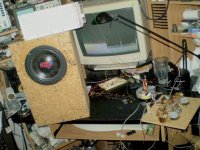
That picture was the very last one taken of my setup the very same night I had burned it up!
In fact if you look close enough you can see a big hole in the diaphragm but the stator's were burned beyond repair that time.
The other one got accidentally damaged with a ripped stator screen when something fell of it.
I tried repairing it but I could never get it much past 6KV without it arcing after that.
I got tired of trying to repair them so I just let it go and see how far I could get and the last measurement it was +110db when it failed and the screen turned cherry orange from the heat like a tube filament!!
But Hey, At least I got the data I was looking for for my new design.
Just to remind you all of my latest tests were done using a mono setup so that I could hear exactly what was going on with just one setup and not too make matters worse and be confused with the stereo signal.
What I was hearing from that one channel just blew my mind and I can't wait to get all of what I have learned into a working stereo system again.
Only this time just for listening and not taking it to and past any limits causing failure.
I do remember how they sounded back in 2003 when I First made them without a woofer system and in stereo, and, Impressive wasn't even the word for them.
When I First got them back working again in 2010 I sat and listened to just one channel then as well.
And at a low level in Full Range and nearfield and I literally sat there with my jaw on the floor in disbelief as to what I was hearing!!!
Since that time (2010) for 3 years I have been finding out what it takes to get the most out of them and how much voltage can they really take, and of course burned up the one in the picture in 2013.
The only reason I have not mounted the diaphragm to my newest one is partly laziness, and, also a few changes I need to make to the diaphragm frames as far as the bias connection is concerned since I want to push it up even farther (>+10Kv) .
Although it will work just fine as it is.
The other reason is I want to build a self contained preamp, and, poweramp/interface so that everything isn't sprawled all over my desk.
I have been learning to work with PIC chips for the project and I can't have HV getting into everything at this time.
This way it will be a separate unit and I won't need my big mixer and amplifiers just to run it.
It has been said that a sealed or TL bass units mates the best with ESL's if you can't do a full dipole bass setup.
But I believe a ported system can work as well as long as it is tuned to have a very low group delay.
The little panel mated very well to my 8" sub as it was in a small box and tuned very low.
That sub (two of them made) was for my car and relied on the cabin gain as the port only added about 2db or so to the bottom end compared to a sealed box curve.
But the result was a very transient sub and is not ever boomy at all.
Kansas's "Carry on Wayward Son" and Boston's Forepaly and Long Time" was incredible and the panel matched perfectly and very musical with no booming going on.
The Spin Doctor's is another great test and again it was in mono as shown in the picture.
So my findings is that a ported system can be made to work if some thought is put into it and think musically and not worry about getting any lower than 40Hz.
During that test was the First time I got the ESL to match the efficiency of a woofer and both were getting the same amount of power!!
Listening was Grand from there on out !!! He,he,he,he
I didn't have an SPL meter at that time anymore and I didn't have any RTA software setup yet except my ears and audacity.
But, I do know when it is sounding right. 😉
jer 🙂
It is the horizontal dispersion that you should be concerned about.
Those are typical numbers for a panel with those Dimensions.
I get approximately 15 degrees off center with my 3 to 4 inch wide diaphragm at the point before the high end starts to noticeably drop off at 2 feet away.
We had a lengthy discussion a while back about the possibility using a lens or even horns to help widen the dispersion but I never got to the point of pursuing the experiments.
Look up "Horn Loaded ESL's" and "ESL AMT" and you may find those threads.
I have used True RTA many years ago the free version and then I also had level 2 or something with the 1/3 octave settings.
At the time (10 years ago) this was all new to me and was an incredible tool to have at that time.
Then more and more other programs became widely available too and they were free!!
Not too long ago somebody had started a comparison thread on the free versions and paid versions of RTA software and it was shown that they all pretty much showed the exact or very similar results.
They should since they ought to be all using the very same math involved as well.
it was about 5 years ago when I had started searching for RTA's again and I had discovered that Audacity had a spectrum analysis function so i used that for a while.
Shortly after that I discovered "Visual Analyzer" and that was the First Real Time RTA program that I had used.
Even though it had a tendency to crash a lot it still worked rather well and accurately.
This was the first time that I could actually measure the THD of my speaker system and this means more to me than any of the other spec's stated about drivers in general.
Now more refined than back then "Visual Analyzer" is an incredible work of art for a piece of testing software.
I have used nearly all of the other paid for stuff as well (either cracked versions or trial versions where I had to completely reload the OS from a format to get them to work for 30days or so) some of them i really like but they do cost a lot.
The free versions give you just the same results in that manner.
Some like ARTA and it looks very nice but I have a hard time trying to figure out how to use it to its fullest potential, so I haven't spent much time with it.
REW does have an EQ curve function in it but I don't have an EQ system that it can control at this time.
Most of my system is purely analog and I use my Mackie 32-8's filters when I need to.
I do like the world of VST's a lot and I do mess around with that stuff as well.
I haven't taken the time to properly setup a VST crossover yet but I have tried it out before.
I much prefer an analog system anyhow.
Digital has a big issue with latency but I will look more in to it again when I get more time.
Each order of filter gives a 90 degree phase shift and this is why when you use a second order filter you have to reverse the polarity of one of the drivers.
That is about as much as i know about filter design performance when it comes to phase shift and group delay caused by the filters themselves.
I do know this, when you measure an ESL in the nearfield (to eliminate any room reflections from the measurement) the phase response stays consistent throughout its bandwidth with a flat line for a curve.
The First time I had saw this I was amazed (unless I am just missing something)!!!
Back to when I was using a VST Crossover there was some sort of Phase delay issue going on as I had mentioned and i couldn't keep the signal from localizing the drivers.
I tried various crossover frequency's as I was aiming to get in the 200hz to 300hz range.
600hz was okay although I wanted it lower.
But when I had went back to using the analog filters on my mixer as a makeshift crossover the two drivers naturally crossed over at about 1100Hz or so as shown in the graph.
This is also basically the frequency starting point of Dipole cancellation as well for my size of panel width.
It was at this setting that the two drivers worked in unison with no noticeable phase differences and no localization between the two drivers.
The 5 1/4" driver box used sealed as shown with duct tape and when I uncapped it (as badly tuned as it is from the factory) it was just terrible!!
I am assuming that there is some sort of Phase or group delay issue going on there when the two aren't matching up and working in unison causing localization of the signal with the drivers.
I just never got that far in to investigating this once I got back into it.
That picture was the very last one taken of my setup the very same night I had burned it up!
In fact if you look close enough you can see a big hole in the diaphragm but the stator's were burned beyond repair that time.
The other one got accidentally damaged with a ripped stator screen when something fell of it.
I tried repairing it but I could never get it much past 6KV without it arcing after that.
I got tired of trying to repair them so I just let it go and see how far I could get and the last measurement it was +110db when it failed and the screen turned cherry orange from the heat like a tube filament!!
But Hey, At least I got the data I was looking for for my new design.
Just to remind you all of my latest tests were done using a mono setup so that I could hear exactly what was going on with just one setup and not too make matters worse and be confused with the stereo signal.
What I was hearing from that one channel just blew my mind and I can't wait to get all of what I have learned into a working stereo system again.
Only this time just for listening and not taking it to and past any limits causing failure.
I do remember how they sounded back in 2003 when I First made them without a woofer system and in stereo, and, Impressive wasn't even the word for them.
When I First got them back working again in 2010 I sat and listened to just one channel then as well.
And at a low level in Full Range and nearfield and I literally sat there with my jaw on the floor in disbelief as to what I was hearing!!!
Since that time (2010) for 3 years I have been finding out what it takes to get the most out of them and how much voltage can they really take, and of course burned up the one in the picture in 2013.
The only reason I have not mounted the diaphragm to my newest one is partly laziness, and, also a few changes I need to make to the diaphragm frames as far as the bias connection is concerned since I want to push it up even farther (>+10Kv) .
Although it will work just fine as it is.
The other reason is I want to build a self contained preamp, and, poweramp/interface so that everything isn't sprawled all over my desk.
I have been learning to work with PIC chips for the project and I can't have HV getting into everything at this time.
This way it will be a separate unit and I won't need my big mixer and amplifiers just to run it.
It has been said that a sealed or TL bass units mates the best with ESL's if you can't do a full dipole bass setup.
But I believe a ported system can work as well as long as it is tuned to have a very low group delay.
The little panel mated very well to my 8" sub as it was in a small box and tuned very low.
That sub (two of them made) was for my car and relied on the cabin gain as the port only added about 2db or so to the bottom end compared to a sealed box curve.
But the result was a very transient sub and is not ever boomy at all.
Kansas's "Carry on Wayward Son" and Boston's Forepaly and Long Time" was incredible and the panel matched perfectly and very musical with no booming going on.
The Spin Doctor's is another great test and again it was in mono as shown in the picture.
So my findings is that a ported system can be made to work if some thought is put into it and think musically and not worry about getting any lower than 40Hz.
During that test was the First time I got the ESL to match the efficiency of a woofer and both were getting the same amount of power!!
Listening was Grand from there on out !!! He,he,he,he
I didn't have an SPL meter at that time anymore and I didn't have any RTA software setup yet except my ears and audacity.
But, I do know when it is sounding right. 😉
jer 🙂
- Status
- Not open for further replies.
- Home
- Loudspeakers
- Planars & Exotics
- A Bi-amped ESL/Altec 416 hybrid + subs