Pin 1 is marked by a square pad on the board.
Here's how you identify the pins on a DIP-8 package:
When in doubt consult the manufacturer's data sheet.
~Tom
Here's how you identify the pins on a DIP-8 package:
An externally hosted image should be here but it was not working when we last tested it.
When in doubt consult the manufacturer's data sheet.
~Tom
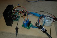
I've been listening to my newly built stereo M86/P86 set for about 5 days now. My enclosure is not finished but I cobbled the amp into a couple setups with 3 different speakers just to have a listen. Played lots of vinyl from a tube pre and also direct direct passive from CD.
Quite enjoyable to my ear - precise and transparent are two words that come to mind. Highly recommended!
Quite enjoyable to my ear - precise and transparent are two words that come to mind. Highly recommended!
Pin 1 is marked by a square pad on the
~Tom
Thank you Tom !
Dominique
I got mine playing today, just powering the midrange drivers of my Kairos active speakers. I am putting my passive crossovers back in so that tomorrow I can hear it full range and compare it other amps I have.
My first impression is very positive. Playing into the SB Acoustic Satori 8ohm (nearly full range) woofers they have a powerful clear sound, very detailed and dense, solid tone. Intense, musical, not suitable for background music! More to come.
My first impression is very positive. Playing into the SB Acoustic Satori 8ohm (nearly full range) woofers they have a powerful clear sound, very detailed and dense, solid tone. Intense, musical, not suitable for background music! More to come.
With the full speakers, wow. Awesome. Detail MONSTER. The low noise floor and balanced signal really allows the micro details to come through. It lets the music sound alive and the tone is natural and very clear. The amp has very good electrical damping so transients sound very strong and confident. If you like tonal texture, this is your amp, perfect for classical music, solo piano/guitar, female voice, etc. I've not tried loud rock or symphony yet as all the kids were asleep by the time I got the speakers playing.
My speakers are 2way, 7ohms min, 87dB sensitivity, and after playing a couple hours the 7x7x2" fins heatsink with two amps was still cool. The backside of the chip itself was about 75F to the touch.
I was using 2ch of my multichannel pro audio DAC tonight, but I'll put my Buffalo/Legato in tomorrow. Should make it even smoother without the output electrolytics of the pro DAC.
12ft of balanced install cable .20/ft sounds as good as 1m of my very expensive audiophile RCA ICs. First time using balanced signal and I like it.
I'm very glad this quality of amp is available to me for <$200/ch! Thanks Tom!
Rich
Rich,
Congrats on getting the build done and thanks for sharing some early impressions.
Bring it on with the heavier music (when time and opportunity allows) ... 🙂
Congrats on getting the build done and thanks for sharing some early impressions.
Bring it on with the heavier music (when time and opportunity allows) ... 🙂
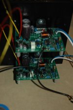
Two of the 22uF caps on the LM3886 DC power are not the solid state caps shown in the manual photo.Almost finished the amps today. Last remaining step is soldering the 3886 after the box is built. Next up is the box, then IC cables.
The Modulus-86s took about 6 hours to build both boards. The Sympaticos went together in about half hour because much of it is SMD, presoldered to PCB.
Do you hear any difference between the LM3886 vs LM3876?In a composite amplifier, such as the Modulus-86, the sound quality is determined mostly by the error-correction op-amp (LME49710).
When listening on my Alpair 6P full-range speakers, the only sonic signature I hear and those of the Alpair 6P (and its enclosure). The amp is transparent, both with the LM3886 and the LM3876. I really like it.
~Tom
Oh, I found the post that said no audible difference.
Last edited:
Do you hear any difference between the LM3886 vs LM3876?
Yes, I am also interested :
http://www.diyaudio.com/forums/chip...-one-produces-better-sound-2.html#post4208742
Thank's.
Phil.
Given the fact that the composite pulls everything right down I would be very suprised if anyone could hear a difference. But won't argue with anyone 'preferring' one of them over the other.
3886 soldering to PCB
A bit of an issue I noticed during assembly, hopefully this will help others avoid a problem...
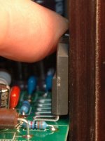
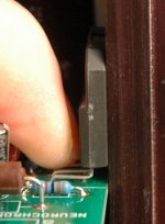
When the chip is placed vertically in the PCB holes, gravity pulls it down and causes it to "slouch" a little, making the bottom edge of the chip duck inside the edge of the PCB and away from the heatsink mounting plane. If you solder it like this it will not contact the heatsink properly and enter protection and sound bad!
When the chip is "slouched," the interference of the PCB past the chip's rear surface plane is about 0.015", or maybe .25mm, just guessing by eye.
When possible, it is best practice to mount power transistors to their heatsink before soldering to the PCB and if this is done the chip is held in the right orientation, cannot slouch, and you will have no interference from the PCB when you do the final mounting. Since this chip requires no insulation from heatsink, so there is no insulation thickness to consider, you can mount it to the heatsink dry for the soldering. If you use a metal backed chip then use the insulation when soldering.
To illustrate the issue: If you place the chip on its back on a flat surface, then slide it into the (vertical PCB) holes the chip stays flat up until the very last smidgeon of insertion, then the back of the chip lifts off the surface when the pins are all the way home. So when the chip is placed vertically into the horizontal PCB, gravity pulls it all the way down and creates the slouch, pulling the chip away from the heatsink plane.
Screwing down the chip first (dry) still allows the PCB to easily slip onto the pins. I wouldn't recommend changing the PCB dimensions because that edge actually makes installing the chip in this way easier because the PCB edge holds the PCB at the perfect height for sliding the vertical PCB onto the horizontal screwed down chip pins. It's like somebody knew what they were doing! 😛
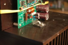
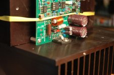
With standoffs screwed on the the PCB, use some kind of right angle reference (I used another heatsink standing vertical) to position the PCB perfectly perpendicular to the horizonal heatsink which has the chip attached. Then tack solder some pins from front and back rows, remove the assembly from the jig and fully solder all the pins on the bottom of the PCB.
In the instruction manual, Tom states:
"14. ICs: U2, U5, and U6. When soldering the LM3886 (U2), ensure that U2 can be mounted to a heat sink without stressing the leads on the IC."
So if you do this step you'll find a way to prevent this issue, but if you just merrily "solder everything together" you'll have problems later mounting to the heatsink because the chip has poor posture and likes to slouch. The interference is too small to notice by eye. You want to be able to place the chip in the middle of the heatsink, not on the edge of the heatsink which would be required if the chip was soldered while slouched.
A bit of an issue I noticed during assembly, hopefully this will help others avoid a problem...
When the chip is placed vertically in the PCB holes, gravity pulls it down and causes it to "slouch" a little, making the bottom edge of the chip duck inside the edge of the PCB and away from the heatsink mounting plane. If you solder it like this it will not contact the heatsink properly and enter protection and sound bad!
When the chip is "slouched," the interference of the PCB past the chip's rear surface plane is about 0.015", or maybe .25mm, just guessing by eye.
When possible, it is best practice to mount power transistors to their heatsink before soldering to the PCB and if this is done the chip is held in the right orientation, cannot slouch, and you will have no interference from the PCB when you do the final mounting. Since this chip requires no insulation from heatsink, so there is no insulation thickness to consider, you can mount it to the heatsink dry for the soldering. If you use a metal backed chip then use the insulation when soldering.
To illustrate the issue: If you place the chip on its back on a flat surface, then slide it into the (vertical PCB) holes the chip stays flat up until the very last smidgeon of insertion, then the back of the chip lifts off the surface when the pins are all the way home. So when the chip is placed vertically into the horizontal PCB, gravity pulls it all the way down and creates the slouch, pulling the chip away from the heatsink plane.
Screwing down the chip first (dry) still allows the PCB to easily slip onto the pins. I wouldn't recommend changing the PCB dimensions because that edge actually makes installing the chip in this way easier because the PCB edge holds the PCB at the perfect height for sliding the vertical PCB onto the horizontal screwed down chip pins. It's like somebody knew what they were doing! 😛
With standoffs screwed on the the PCB, use some kind of right angle reference (I used another heatsink standing vertical) to position the PCB perfectly perpendicular to the horizonal heatsink which has the chip attached. Then tack solder some pins from front and back rows, remove the assembly from the jig and fully solder all the pins on the bottom of the PCB.
In the instruction manual, Tom states:
"14. ICs: U2, U5, and U6. When soldering the LM3886 (U2), ensure that U2 can be mounted to a heat sink without stressing the leads on the IC."
So if you do this step you'll find a way to prevent this issue, but if you just merrily "solder everything together" you'll have problems later mounting to the heatsink because the chip has poor posture and likes to slouch. The interference is too small to notice by eye. You want to be able to place the chip in the middle of the heatsink, not on the edge of the heatsink which would be required if the chip was soldered while slouched.
Attachments
Hi,
I used a little piece of wood (triangular white shape on pict) like this :
I sold only two pins and check vertical and horizontal lines, then I sold other pins..
Phil.
I used a little piece of wood (triangular white shape on pict) like this :
An externally hosted image should be here but it was not working when we last tested it.
I sold only two pins and check vertical and horizontal lines, then I sold other pins..
Phil.
That PCB is a disaster waiting to happen.A bit of an issue I noticed during assembly, hopefully this will help others avoid a problem............................
The layout designer needs to be sacked !
The PCB must not project past the back face of the chipamp and preferably 10mil less than that to allow for tolerances of the components.
You could fit a thick copper shim to bring the chipamp thermal interface back to meet the heatsink.
he tells you !If you solder it like this it will not contact the heatsink properly and enter protection and sound bad!
Overheating, because the chip pulls off the heatsink due to thermal expansion/movement and the long distance = poor clamping of the offset bolt location.
It takes very little force to pull off the chip.
Phil's post pic on the other hand looks like there is a deliberate gap so that the chip can contact the heatsink properly.
Last edited:
That PCB is a disaster waiting to happen.
The layout designer needs to be sacked !
The PCB must not project past the back face of the chipamp and preferably 10mil less than that to allow for tolerances of the components.
You could fit a thick copper shim to bring the chipamp thermal interface back to meet the heatsink.
Thanks Andrew. I was able to install the chip perfectly, but I had to think about it first. That's why I'm passing on the technique that enabled easy perpendicular perfect chip installation. I think the coplanar PCB edge made it easier than without it. The pins were perfectly aligned in the center of the holes.
I don't know if follows traditional layout rules, but the sound quality certainly warrants any exceptions. I've not heard every chip amp, but I've heard a few bad ones with famous names.
The edge of the PCB does not project past the face of the chipamp, except when the chip is installed at a slant, which is the fault of the chip's pins, and would sit crooked on any flat PCB. On PCBs with extra edge clearance, and installed without a perpendicular alignment jig the chip would be angled and would need the pins bent on final install. So this is good info for any chip amp build. I'm sure most of the seasoned builders here know how to do it correctly, but this kit has excellent instructions written in layman terms along with internet rumors of good sound quality will attract flocks of noobs for their first project.
If there was more clearance on the PCB and the chip was screwed down before soldering then hole alignment would not be as easy or precise as it it now. The edge of the PCB is coplanar with the rear side of the chip when holes and pins are lined up. Seems like a good feature?
Attachments
There should be a gap.
This gap allows for tolerances as I stated and also allows for thermal expansion as I stated.
The PCB as designed deserves a caution statement in the instructions, to ensure the builder does as you did and makes sure the PCB does not project out the back.
If by oversight the PCB did project out beyond, then the disaster is as stated "waiting to happen".
An externally hosted image should be here but it was not working when we last tested it.
Hope this helps.
Phil.
- Home
- Amplifiers
- Chip Amps
- Modulus-86 build thread