snowy day, hadn't fired up LTSpice in a while...
can't see how its going to be stable
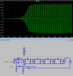
the dotted box is a crude linear "macro model" for LM3886 with enough excess poles that it is unstable at below ~ Av 5
happy with gains of 10+ like expectation from the data sheet min gain spec
if you have a stable prototype it aint wired like the pdf, from my sim
can't see how its going to be stable
the dotted box is a crude linear "macro model" for LM3886 with enough excess poles that it is unstable at below ~ Av 5
happy with gains of 10+ like expectation from the data sheet min gain spec
if you have a stable prototype it aint wired like the pdf, from my sim
Attachments
Last edited:
so show me the sim or circuit error
Huh? I never simmed this circuit, it's not complex enough to need it.
my sim .asc file is right there for any to download, dissect show me the error
until then I maintain you didn't build that
whatever you did build, are listening to ain't the circuit shown
until then I maintain you didn't build that
whatever you did build, are listening to ain't the circuit shown
Jesus... Am I getting accused of not building the circuit I said I did?
I don't even see the point in that.
I don't even see the point in that.
its possible there are wiring and/or component value differences from the circuit shown and what you have
but it seems rather unlikely you have a non-oscillating build to the shown circuit diagram
so until anyone can show me my sim error I have to give the warning
but it seems rather unlikely you have a non-oscillating build to the shown circuit diagram
so until anyone can show me my sim error I have to give the warning
So you're saying that I built AND published a circuit that doesn't work.
As I say, I've built 4 boards thus far (a friend is building another two), AND a point-point prototype so I'd know if I had made an error in component values.
I am well aware of how good LTSpice is, but you're testing a circuit with a different opamp model and an approximate LM3886 and yet you say that your simulation emulates my real life circuit?
Your LTspice model does not take into account the internal compensation of the LM3886 for example.
the integrator feedback around the LT1469 renders the exact op amp pretty irrelevant
my LM3886 model isn't what I would call pessimistic but there is the possibility that all parts built today on modern processes are better than the typical specs in the decades old datasheet
but as an engineer I expect to actually design to worst case datasheet info with a margin
I wouldn't recommend building that circuit, with those values to any manufacturer as a safe practice
can't see giving a pass to anyone recommending such to hobby builders with even less electronic design sophistication, or even a decent oscilloscope
the integrator feedback around the LT1469 renders the exact op amp pretty irrelevant
True
my LM3886 model isn't what I would call pessimistic but there is the possibility that all parts built today on modern processes are better than the typical specs in the decades old datasheet
Probably not the case IMO.
but as an engineer I expect to actually design to worst case datasheet info with a margin
I wouldn't recommend building that circuit, with those values to any manufacturer as a safe practice
Fair enough if you wouldn't recommend it. I'm not saying anyone should build it and I'm not here to sell it. I posted it here in case it interests anyone, and if they build it and like it then great.
But there's no point in saying it won't work and must be unstable because of some approximations you've made. If you build it and then find problems then great, I will accept that. It's things like this that deter me from posting on this forum (and most other forums).
Last edited:
Anyway, what strikes you as being so awful about this circuit?
This is a totally standard composite topology. It has proven to be completely stable in practice...
This is a totally standard composite topology. It has proven to be completely stable in practice...
I suspect that only so much can be done with this topology though, it's quite simple compared to most of the ones that I see.
It's a relatively simple topology, but it is one that has a lot of hidden trap doors in it... Stability is the obvious one. Stability in the global loop is relatively straight forward to deal with, but local stability on the LM3886 is actually a bit dicey. I've seen several setups where the global loop has been stable, but the LM3886 will oscillate at a low(-ish) amplitude in the 2-10 MHz frequency range. Ensuring that the circuit recovers (somewhat) gracefully from overload can be tricky as well.
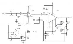
The circuit may look simple on the surface, but it definitely warrants simulation. In particular, I'm a bit skeptical of the local feedback around the LM3886. The LM3886 is stable for gains of 10 and above (not including the quasi-oscillation in its output stage as mentioned in the data sheet). You have it operating at a gain of 4.7...
~Tom
Last edited:
the real stability margins can be tested in hardware - Ridely Engineering makes complete instruments for assessing feedback loops
can also be done with relatively low cost parts:
but the sim route is certainly the least effort and you should address why you believe it is misleading when it gives negative phase margin, obvious oscillation
to me the minimum requirement for a op amp model is to show oscillation at a fraction of its datasheet minimum gain spec - pretty useless to debug circuits using those op amps if the model won't show problems where the datasheet warns of them
can also be done with relatively low cost parts:
P.S. In case you are wondering how to build a decent loop gain probe: http://lib.ugent.be/fulltxt/RUG01/002/033/143/RUG01-002033143_2013_0001_AC.pdf ch. 5.1.3 and the following. Attached is a picture of such a loop gain probe, and the results of measuring a wideband 2 pole compensated opamp (it's not a commercial type, but a building block in a mixed signal IC design library).
but the sim route is certainly the least effort and you should address why you believe it is misleading when it gives negative phase margin, obvious oscillation
to me the minimum requirement for a op amp model is to show oscillation at a fraction of its datasheet minimum gain spec - pretty useless to debug circuits using those op amps if the model won't show problems where the datasheet warns of them
Last edited:
A Rogowski transformer and a network analyzer (I use an HP 3577A) are valuable tools for correlating simulation and reality re. loop gain and phase/gain margin.
~Tom
~Tom
I've tested this circuit pretty rigorously and basically I can't make it go unstable. It recovers instantly from shorts too. No oscillation anywhere either.
Tom, your point on instability with gains of less than 10 on the LM3886 is duly noted, I will revise the values for a gain of 11 on the LM3886.
As for the simulation, I'll do some simming on TINA when I have more time. It has more accurate models for the parts in question.
Tom, your point on instability with gains of less than 10 on the LM3886 is duly noted, I will revise the values for a gain of 11 on the LM3886.
As for the simulation, I'll do some simming on TINA when I have more time. It has more accurate models for the parts in question.
I need to rework my model some more - now look like your circuit has all of 12 degrees phase margin when I tried to get closer to the datasheet typ GBW
as for the Tina model I was disappointed to see:
is it really any good for gain/phase - did anyone see a update?
as for the Tina model I was disappointed to see:
Distortion of opamp spice models is NEVER assumed to be realistic, this also stated in most any serious model file.
But the real bummer is elsewhere. I did a quick check and found that that the bode plot is completely off, indicating a unity stable amp and in fact it sims like this in a transient analysis (WTF!). GBWP is set to datasheet max of 8Mhz, not 4Mhz (typical for the real part). Open-loop phase hits 120deg at over 10Mhz, while in reality and datasheet this point is at below 1Mhz.
For correct AC analysis and stability checks the model seems to be useless.
EDIT: see my take on a correct bode plot estimation here.
Obviously nobody at NS/TI checked the model, otherwise the "mute bug" and the wrong gain/phase response would have been readily detected BEFORE publication.
All in all I'm not impressed.
is it really any good for gain/phase - did anyone see a update?
I won't dispute that IOS390 has a running prototype but I agree with the others that must be really on the edge of going unstable with that gain of 5.7x. 10x is lowest gain for LM3886 and already not exactly a conservative design.
I have a very similar composite (49720+LM4780) which runs way more local compensation for the master OP just to be safe at any conditions, this also needs local and global gains to be the same.
I have a very similar composite (49720+LM4780) which runs way more local compensation for the master OP just to be safe at any conditions, this also needs local and global gains to be the same.
I'll modify it so that the gains as suggested.
As I said before I have a broken function generator (cheap Siglent crap), so I can't test anything right now.
As I said before I have a broken function generator (cheap Siglent crap), so I can't test anything right now.
I've tested this circuit pretty rigorously and basically I can't make it go unstable.
I guarantee you that I can... 🙂 Run a square wave with a high edge rate (say 10-100 ns rise time) into the amp and turn up the amplitude until the amp is within a few hundred mV of clipping. I guarantee you that it will oscillate. Then bring the input amplitude down and watch how the amp continues to oscillate.
Do the same thing with a sine wave and you'll notice oscillation near the peaks as well.
There is one interesting point about composite amplifiers: It is possible to obtain stability in the global feedback loop while the stability of the inner loop is marginal. This will result in a rather poor transient response, but it will be stable. That's probably the case in your circuit.
As for the simulation, I'll do some simming on TINA when I have more time. It has more accurate models for the parts in question.
I find the TINA model to be optimistic on phase margin and bandwidth. In the lab I get a phase margin that's about 10~15 º lower than that predicted by TINA. In simulation, I aim for 75~90 º PM to ensure that I have 60~75 º PM in reality.
The TINA model seems pretty accurate for AC analysis and transient simulations. It contains no modeling of the supply current(!), so you will not be able to simulate anything related to PSRR - or even the total supply current drawn under load - which is as pretty remarkable bug. I can live without the MUTE circuit being modeled.
These simulations are my minimum suite:
Loop gain/phase (stability) - noted PM, GM, UGBW, loop gain at 20 kHz.
Closed loop gain
Closed loop transient response (10 kHz, square wave, 10~20 Vp out).
Closed loop transient response vs load cap.
Closed loop transient response vs input voltage. Start at just below clipping, continue past clipping.
Closed loop transient sim with sine wave input vs input voltage. Start just below clipping, continue past clipping.
I run the simulations both with a simulated speaker load and the normal 8Ω||Cload arrangement. In the lab, I always test stability with a capacitive load (8 Ω || Cload).
I have had many, many circuits that show stellar performance, both AC and transient, fall apart once the output voltage approaches the supply rails.
Also, I strongly suggest including the parasitics of the passive components in the simulation. In particular, the parasitics on the feedback resistor (and associated routing) can provide some nasty surprises. That's where the Zobel filter is handy... Expect a story about that on my Taming the LM3886 website.
~Tom
Last edited:
- Home
- Amplifiers
- Chip Amps
- LM3886 & LME49720 composite amp