You're the second person to suggest dropping R5/R12 from 1 mOhm to 100K. What is the rationale for this?
...
I don't know if it matters, but keep in mind the buffer is for receiving high input impedance signals (guitar pickups).
Bear in mind that the feedback circuit is part of the op amp, it's made exterior so gain will be adjustable.
This means, among other things, that the feedback circuit has nothing to do with the input circuit, or input impedance (Zin). You have:
Input circuit ~> op amp ~> output circuit. All different circuits.
(these might or might not be connected together in some way, but they're still different)
That this is used with guitar pickups matter a lot, because you want a very high Zin such as one-half or one meg. Ordinarily you'd see a Zin of something like maybe 10-50k.
.
The + input handles the high impedance part. The - input is for setting the gain, and is best at lower impedances for better hf response.
You don't want a bipolar op amp with this high impedance circuit. Even 1M for R11 is a much higher value than most would use there.
Okay. FYI, if it matters I'm planning on using OPA2134 opamps (it's a dual channel board like pictured in OP and I'm using both channels).
So you're saying using too high a value for R4/R11 (feedback resistor) will compromise the high frequency performance of the opamp?
So I could then set R4/R11 at 100K (feedback), and R5/R12 (to ground) become ~47K.
On the other hand, what happens if I drop R5/R12 too low? Ie. Is there any performance loss with going down from 1M vs. 50K?
Signal to noise is more important for me that too much high frequency perfection if that plays a role.
Only R4 and R5 affect--control--gain.
The purpose of C7 is twofold.
1. Some capacitor of some size is always needed in that location to block DC in a single-supply circuit, which this is.
2. It restricts DC gain to unity. The DC that's of concern is just errors that every op amp has.
However, the value of 10nF is small, really small. Does this thing have any bass at all? Suspecting no.
.
You're talking about C3 (10 nF) which is the capacitor to ground. If I'm changing that ground resistor I'll have to change that too I know. I'm wondering about the 100 pF C7 in parallel across the feedback resistor.
Thanks guys.
Last edited:
You're talking about C3 (10 nF) which is the capacitor to ground.
Jeeze! Yes I am. I think I'll go take a nap or something. Maybe watch some football if there's any on.
.
Jeeze! Yes I am. I think I'll go take a nap or something. Maybe watch some football if there's any on.
.
lol. Don't sweat it. I'm learning from your explanations and you've been very helpful nonetheless. 🙂
I'm wondering about the 100 pF C7 in parallel across the feedback resistor.
But just to finish the thought, C7 has lower resistance (reactance) at higher frequencies. Lower resistance means more of these high frequencies feed back, which means less gain. Helps prevent oscillation, among other things.
Game...gotta be a game on someplace...
.
.
<< Helps prevent oscillation, among other things. >>
The "other things" are the effect C7 has on audio frequencies, if any. This is a decision made by the circuit designer.
...any buffalo wings around here...?
.
<< Helps prevent oscillation, among other things. >>
The "other things" are the effect C7 has on audio frequencies, if any. This is a decision made by the circuit designer.
...any buffalo wings around here...?
.
So I could then set R4/R11 at 100K (feedback), and R5/R12 (to ground) become ~47K.
On the other hand, what happens if I drop R5/R12 too low? Ie. Is there any performance loss with going down from 1M vs. 50K?
That op amp should be ok in this case.
The R5 or R12 and the caps set the lf rolloff. Usually you want it around 1-10Hz.
If R5=50k, then for 10Hz bandwidth, C3=1/(2*3.14*10*50k) or 0.33uF.
For 1Hz, it's 3.3uF.
That op amp should be ok in this case.
The R5 or R12 and the caps set the lf rolloff. Usually you want it around 1-10Hz.
If R5=50k, then for 10Hz bandwidth, C3=1/(2*3.14*10*50k) or 0.33uF.
For 1Hz, it's 3.3uF.
So just out of interest, for sake of understanding, what would happen if you dropped R5/R12 down even further, eg. to 1K? or 100 ohms? (Assuming you change the C3 cap accordingly as well.)
Thanks for the C3 suggestion btw.
Hi,
Its amazing how something so simple can be misconcieved.
Basically reduce R5 and increase C3, both a lot, R5 to 2.2K.
Still I'm bemused about what R3 and R10 are connected to.
The circuit isn't sensible for purpose, i.e. a guitar buffer.
R4 is way too low, and what are C3 and R5 doing ?
rgds, sreten.
So just out of interest, for sake of understanding, what would happen if you dropped R5/R12 down even further, eg. to 1K? or 100 ohms? (Assuming you change the C3 cap accordingly as well.)
Is this with R4/R11 still =1M? Then the gain would increase proportionately.
The gain factor (not in dB) is = 1 + (R11/R12).
Last edited:
Is this with R4/R11 still =1M? Then the gain would increase proportionately.
The gain factor (not in dB) is = 1 + (R11/R12).
Sorry. No I meant, if you reduce R4/R11 proportionately as well. ie. Just reduce everything (R5/R12 & R4/R11) down even further, but in the same ratio so it's gain equivalent.
Surely there's a point you would reach when you'd have a problem, no? ie. What happens when these R5/R12 resistors go too low?
Hi,
Its amazing how something so simple can be misconcieved.
Basically reduce R5 and increase C3, both a lot, R5 to 2.2K.
Still I'm bemused about what R3 and R10 are connected to.
The circuit isn't sensible for purpose, i.e. a guitar buffer.
R4 is way too low, and what are C3 and R5 doing ?
rgds, sreten.
So then I take it you would agree with changes as follows:
R4 50K in series with 250k audio taper potentiometer to give variable 0-17 dB gain
R5 50K
C3 0.33 uF
Sorry. No I meant, if you reduce R4/R11 proportionately as well. ie.
Just reduce everything (R5/R12 & R4/R11) down even further, but in the same ratio so it's gain equivalent.
Surely there's a point you would reach when you'd have a problem, no? ie.
What happens when these R5/R12 resistors go too low?
If R4/R11 are below 1-2k, they would stress the op amp output current limits.
If R5/R12 are too low, the caps would be very large.
So just out of interest, for sake of understanding, what would happen if you dropped R5/R12 down even further, eg. to 1K? or 100 ohms? (Assuming you change the C3 cap accordingly as well.)
Thanks for the C3 suggestion btw.
There is a limit to reducing these resistors. The opamp will only drive a given load, and these are part of that load. Keeping them fairly high means that you will not need to resort to an electrolytic or other exotic to get a decent quality cap in the size you want. I don't think it'll compromise noise performance in the context of a guitar amp.
If R4/R11 are below 1-2k, they would stress the op amp output current limits.
If R5/R12 are too low, the caps would be very large.
There is a limit to reducing these resistors. The opamp will only drive a given load, and these are part of that load. Keeping them fairly high means that you will not need to resort to an electrolytic or other exotic to get a decent quality cap in the size you want. I don't think it'll compromise noise performance in the context of a guitar amp.
Thanks for the explanations. So as long as we're talking 50K for R4/R11, it shouldn't affect output signal to noise performance?
I'm not going out to a guitar amp. I'm going into my soundcard DAW and I'm trying to maintain at least -100 dB noise floor even after boosting the signal with the opamp ~10 dB.
So signal to noise is important.
Not that it matters since I'm not powering from batteries, but is it correct that with a lower R4/R11 since it increases the opamp output current, it means the opamp would need to draw more current to function? ie. In a battery operated circuit you'd rather these at 1M than 50K?
Last edited:
How about a switchable gain?
2times (+6dB) and 4times (+12dB).
Those cover most low output to medium output Sources and use 1times (+0dB) for your high level sources.
Then you can optimise the stability margins at the two preset gain values so that the margins are the same no matter which gain is switched in.
Using a pot in the feedback loop to change gain, WILL VARY the stablity margins and this is likely to be very audible, if you get it wrong.
How about a switchable gain?
2times (+6dB) and 4times (+12dB).
Those cover most low output to medium output Sources and use 1times (+0dB) for your high level sources.
Then you can optimise the stability margins at the two preset gain values so that the margins are the same no matter which gain is switched in.
Using a pot in the feedback loop to change gain, WILL VARY the stablity margins and this is likely to be very audible, if you get it wrong.
I'm not sure what mean by "optimizing the stability margins".
The parts I am looking at substituting are:
R4 50K in series with 250k audio taper potentiometer to give variable 0-17 dB gain
R5 50K
C3 0.33 uF
Why would there be any instability of any kind?
The OPA2134 opamp should be more than able to provide 17 dB gain at 300K max for R4. And at 0 ohms on the pot, R4 is 50K which should also be stable.
What instability are you referring to?
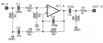
For quicker re-reference, I have re-attached the schematic.
Attachments
Normally we select a gain for an amplifier and then compensate to get the stability margins we require for correct operation.
Change the gain and the compensation will have to change to match the new gain.
You are aiming for an adjustable gain. That will require a range of different compensations, each chosen to suit the gain currently set with the adjustable knob. I think you will find it impossible to achieve a consistent set of compensations to give the required stability margins.
Just asking for two gain settings on a switched gain block is a big enough challenge for someone who does not know about compensation and stability margins.
.
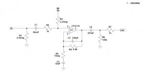
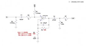
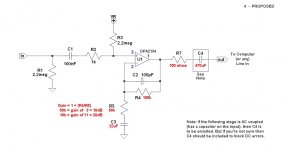
Due to being easily amused I've redrawn the circuit from post #37 in a more conventional way. Also posted a proposed circuit with some of the suggested changes made. This might help, might not, I dunno.
Still one problem remains. How is the thing powered? Assuming R3 to be one-half of a voltage divider (albeit misapplied), where's the other half? Or is R3 actually supposed to go to ground? Maybe something I don't know about? More I dunno.
PS it seems there's little point in using an OPA2134 as a buffer, since it has ridiculously high Zin (input impedance) to begin with.
.
Attachments
Last edited:
Normally we select a gain for an amplifier and then compensate to get the stability margins we require for correct operation.
Change the gain and the compensation will have to change to match the new gain.
You are aiming for an adjustable gain. That will require a range of different compensations, each chosen to suit the gain currently set with the adjustable knob. I think you will find it impossible to achieve a consistent set of compensations to give the required stability margins.
Just asking for two gain settings on a switched gain block is a big enough challenge for someone who does not know about compensation and stability margins.
I think I understand what you mean. I assume you mean the bias resistor won't be matched if there is an adjustable feedback resistance pot. So that won't work. Agreed. Fixed gain it is.
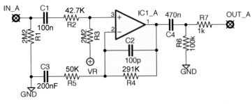
I've edited the schematic with all the changes I'm thinking of.
I've got 291K feedback resistor R4, 50K resistor R5 to ground (gives 16.7 dB gain). I set the bias resistor at the positive input of the opamp R2 to the parallel resistance of these two other resistors, which comes to 42.7K.
Ground capacitor C3 I set at 200 nF to filter at 16 hz.
Is this a reasonable design? Anything else that should be changed?
Thanks everyone. Getting there. 🙂
Attachments
- Status
- Not open for further replies.
- Home
- Source & Line
- Analog Line Level
- Adding a (variable) gain boost to this non-inverting opamp buffer circuit?