Adding a (variable) gain to this non-inverting opamp buffer circuit?
I am wondering how I might go about modifying the attached circuit to add maybe ~10 dB boost to it. ie. What values would I change R4/R5 (and R11/R12) to?
Also would it be possible to work in a variable pot to give maybe -60 db (or even -20 db) to +15 db or +20 db gain control?
Thanks.
I am wondering how I might go about modifying the attached circuit to add maybe ~10 dB boost to it. ie. What values would I change R4/R5 (and R11/R12) to?
Also would it be possible to work in a variable pot to give maybe -60 db (or even -20 db) to +15 db or +20 db gain control?
Thanks.
Attachments
Last edited:
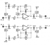
My understanding is gain across the non-inverting opamp is governed by the relationship between R4 and R5 in this circuit (looking at circuit A).
Av = gain
Av = 20*LOG ( 1+R4/R5)
Ie. If R4 was increased to ~2M I would get ~10 dB gain?
Would this work as a straight change and if so should I change C2/C7 also?
Av = gain
Av = 20*LOG ( 1+R4/R5)
Ie. If R4 was increased to ~2M I would get ~10 dB gain?
Would this work as a straight change and if so should I change C2/C7 also?
Last edited:
Also, if anyone's wondering it's a guitar buffer circuit, made for taking high impedance inputs (guitar pickups).
That would be much more repeatable
This circuit has a rather large loss, over -40dB.
If you want even higher loss, why not do this passively with an input attenuator that can be switched out for less loss?
The op amp stage should have a gain of +20dB, and the input attenuator a loss of 0 to -20dB.
That said, it's possible to place the pot in the feedback loop to have a wide range of loss/gain, if the op amp is unity gain stable.
A multi-position make before break switch in the feedback loop would be better than the pot if you just want just a few gain selections,
and would be much more repeatable.
I am wondering how I might go about modifying the attached circuit to add maybe ~10 dB boost to it. ie.
What values would I change R4/R5 (and R11/R12) to?
Also would it be possible to work in a variable pot to give maybe -60 db (or even -20 db) to +15 db or +20 db gain control?
This circuit has a rather large loss, over -40dB.
If you want even higher loss, why not do this passively with an input attenuator that can be switched out for less loss?
The op amp stage should have a gain of +20dB, and the input attenuator a loss of 0 to -20dB.
That said, it's possible to place the pot in the feedback loop to have a wide range of loss/gain, if the op amp is unity gain stable.
A multi-position make before break switch in the feedback loop would be better than the pot if you just want just a few gain selections,
and would be much more repeatable.
Last edited:
You have to include the impedance of c3. It will be high so gain is about 1.
Thanks Paul. I'm not sure what you mean though.
According to this:
Non-Inverting Amplifier | Op Amp Circuit | Radio-Electronics.com
Regarding C3: "The value of this capacitor must be chosen to give a low impedance at low frequencies. It is typically chosen to be equal in impedance to [R5] at the lowest frequency required - this will give a -3dB fall at this frequency."
So I'm using this calculator:
Capacitive reactance calculator reactance capacitor frequence - sengpielaudio Sengpiel Berlin
Which says if I'm using it right, the 10 nF capacitor provides ~1 mOhm reactance at 16 hz. So it seems to be a properly chosen capacitor.
Are you saying I need to integrate this value for C3 into my formula? ie.:
Av = 20 * LOG [1 + R4/(R5+C3)]
R4 = [10^(Av/20) -1] * (R5+C3)
So for 10 dB gain, using resistance at 20 hz:
R4 = (10^0.5 -1) * 1.796 mOhm
R4 = 3.88 mOhm
😕
Thanks.
Last edited:
That's bizarre. It's supposed to be a unity gain buffer:This circuit has a rather large loss, over 40dB.
Micro Buffer MkII | Coldcraft Effects
It's meant to take the high impedance guitar signal and turn it to a low impedance one on output though, if that's what you're referring to.
😕
That's bizarre. It's supposed to be a unity gain buffer:
Yes, it is. The gain (actually loss) is close to R11 / R12 , or 6.8k/1M .
I'd start over with your own circuit design, but you could use this board and change the parts, if you want.
Do you want to use this on a single 9V battery, or what?
Last edited:
The gain (actually loss) is close to R11 / R12 .
The calculation for this is as follows, is it not?
Av = gain
Av = 20*LOG ( 1+R11/R12)
Av = 20 * LOG (1 + 6.8/1000)
Av = 0.059 dB
Basically unity. I see no reason to design my own circuit when this a perfect, compact PCB for a standard non-inverting opamp buffer is available to me and all I have to do is tweak one or two resistors to get the gain I want.
I really just want ~10 dB fixed gain. Anything else would be gravy.
It's not a unity gain buffer.
Forget the dB's. Do the calculation for gain = 5 or gain =10. You should get wholenumber answers. Start the calculation with decade values for the known resistor. Megohms are a bit high for the feedback. I know it's a guitar circuit, but we don't to add appreciable noise, but we don't want to go down too low, because the caps get big, so ~ 100k -> 1 Megohm.
Forget the dB's. Do the calculation for gain = 5 or gain =10. You should get wholenumber answers. Start the calculation with decade values for the known resistor. Megohms are a bit high for the feedback. I know it's a guitar circuit, but we don't to add appreciable noise, but we don't want to go down too low, because the caps get big, so ~ 100k -> 1 Megohm.
According to my calculation, it's a +0.059 dB gain buffer currently, which is the same thing as far as I'm concerned. What am I calculating wrong?It's not a unity gain buffer.
Forget the dB's. Do the calculation for gain = 5 or gain =10. You should get wholenumber answers. Start the calculation with decade values for the known resistor. Megohms are a bit high for the feedback. I know it's a guitar circuit, but we don't to add appreciable noise, but we don't want to go down too low, because the caps get big, so ~ 100k -> 1 Megohm.
So you're saying you would change R5 from 1M to 100K? I'm not understanding what the benefit of this is. If this is going to increase the noise floor I can't see any reason I would. I don't care what size the C3 cap is unless it's compromising performance.
I am wondering how I might go about modifying the attached circuit to add maybe ~10 dB boost to it. ie. What values would I change R4/R5 (and R11/R12) to?
Also would it be possible to work in a variable pot to give maybe -60 db (or even -20 db) to +15 db or +20 db gain control?
Thanks.
To answer your question, 10dB is a gain of about 3. You'd apply the gain formula for non-inverting circuits: Gain = 1 + (R4/R5).
For a buffer R4 would equal R5. As is you're set up for negative gain (R5 is larger than R4). Speaking only for myself, I can't see exactly what you have in mind.
.
To answer your question, 10dB is a gain of about 3. You'd apply the gain formula for non-inverting circuits: Gain = 1 + (R4/R5).
However, as is you're set up for negative gain (R5 is larger than R4). Speaking only for myself, I can't see exactly what you have in mind.
.
How is it negative gain with the stock values to begin with?
Gain = 1 +R4/R5
Gain = 1+ 6.8/1000
Gain = 1.0068
That's positive gain.
Also, I did that calculation the second reply into the thread. I came up with R5= 1 mOhm, R4= 2.2 mOhm. I'm just asking if this makes sense, if I'm making an error, or if I should be changing other components to go along with the increased R4.
Last edited:
.
Whoops, you're right and I misspoke. I was thinking sideways.
But then, I don't at all see the purpose of such a resistor setup in the first place. If you want a buffer, make them equal. If you want gain, apply the formula.
It's actually a kinda bizarre way to go about building a buffer, as far as I know. Usually there's a jumper from pin 1 to pin 2, or maybe a 100 ohm resistor, and that's the end of it.
.
I really just want ~10 dB fixed gain. Anything else would be gravy.
Sorry, that's right, I thought this was an inverting circuit. If you change all the parts near the negative input, you could raise the gain to +20dB.
The cap to ground would have to be much larger to preserve the bass, since the 1M sets the roll off with it.
For example, if the C6 is 1uF and R12 is 100k, then R11 = 910k would give a gain of about +20dB.
.
Whoops, you're right and I misspoke. I was thinking sideways.
But then, I don't at all see the purpose of such a resistor setup in the first place. If you want a buffer, make them equal. If you want gain, apply the formula.
It's actually a kinda bizarre way to go about building a buffer, as far as I know. Usually there's a jumper from pin 1 to pin 2, or maybe a 100 ohm resistor, and that's the end of it.
.
Fair enough, but honestly it's not really important to me what the original design intent was with the 6.8K resistor, since I'm changing that value anyway. I'm using this because it's a prefab tiny PCB which has all the places I need for all the components I need.
Do you know if those values for ~10 dB gain look okay? ie. R4 =1 mOhm, R5 = 2.2 mOhm? Would I need to change C7 as well?
Last edited:
Sorry, that's right, I thought this was an inverting circuit. If you change all the parts near the negative input, you could raise the gain to +20dB.
The cap to ground would have to be much larger to preserve the bass, since the 1M sets the roll off with it.
For example, if the C6 is 1uF and R12 is 100k, then R11 = 910k would give a gain of about +20dB.
You're the second person to suggest dropping R5/R12 from 1 mOhm to 100K. What is the rationale for this?
Cost and size of components are irrelevant to me. I want the best performance only.
I don't know if it matters, but keep in mind the buffer is for receiving high input impedance signals (guitar pickups).
Last edited:
Well honestly it's not really important to me what the original design intent was with the 6.8K resistor, since I'm changing that value anyway. I'm using this because it's a prefab tiny PCB which has all the places I need for all the components I need.
Do you know if those values for ~10 dB gain look okay? ie. R4 =1 mOhm, R5 = 2.2 mOhm. Would I need to change C7 as well?
Only R4 and R5 affect--control--gain.
The purpose of C7 is twofold.
1. Some capacitor of some size is always needed in that location to block DC in a single-supply circuit, which this is.
2. It restricts DC gain to unity. The DC that's of concern is just errors that every op amp has.
However, the value of 10nF is small, really small. Does this thing have any bass at all? Suspecting no.
.
You're the second person to suggest dropping R5/R12 from 1 mOhm to 100K. What is the rationale for this?
I don't know if it matters, but keep in mind the buffer is for receiving high input impedance signals (guitar pickups).
The + input handles the high impedance part. The - input is for setting the gain, and is best at lower impedances for better hf response.
You don't want a bipolar op amp with this high impedance circuit, btw. Even 1M for R11 is a much higher value than most would use there.
For a gain of x10 (20dB) this means that R12 is 100k if R11 is around 1M, since the gain is (1 + R11/R12).
the
Last edited:
- Status
- Not open for further replies.
- Home
- Source & Line
- Analog Line Level
- Adding a (variable) gain boost to this non-inverting opamp buffer circuit?