Thanks for your help Doede, it was a burned out track on the underside of the PSU board, I must have shorted it out somehow when I moved the DDDAC, nothing is screwed down in the case, so it can move around which is not helpful. Time for me to sort this out I think.
ok, good luck getting it tidying up 🙂
ok, see your Point... yes that is correct. if you only need a few hundred mV there is no need for large Vcc. also distortion is very low at that level, so why would you want to decrease that any further.
While I don't have access to an AP test instrument, I've measured the PCM1794A's single-ended output THD at 0.0022% across a 75 ohm resistor I/V @ 200mV RMS via my PC sound card. While good, that result still is less than than what the PCM1794A is capable when operated in to a virtual ground node. Therefore, I had been wondering whether increasing the Vcc above 5V might be employed as an simple means by which to lower the THD closer toward the PCM1794A's true capability even though driving a non-virtual ground impedance, such as an resistor I/V.
Last edited:
Are you focussing on the wright gain features? Who need this redicilous low THD where your loudspeakers are performing perfect when THD is below a few percent?
But that is just a me and my humble opinion of course....
But that is just a me and my humble opinion of course....
Are you focussing on the wright gain features? Who need this redicilous low THD where your loudspeakers are performing perfect when THD is below a few percent?
But that is just a me and my humble opinion of course....
I'm not looking to get in to a debate about what constitutes sufficiently low THD. We all know that there are many sources of distortion beyond that produced by a DAC, or an amplifier for that matter. The distrotion produced by loudspeakers isn't even the worst source, as your ears can internally produce far more distortion still. I was simply curious as to whether increasing the Vcc would move the THD closer to that which the DAC is capable when drivng a virtual ground. As I mentioned, I've been experimenting with the PCM1794A for some time, so my inquirey was simply in support of my further experiments.
Thanks Ken, you are right, no need for debate on this of course.
What is clearly visible is the fact that when you stay away from the VCC boundaries, say like 200mV versus 5 or 8 volt the THD drops dramatically. Also what I see is that only a bit d2 remains. I reach easily the .001% as long as I keep thing running at lower voltages.
Interesting point of the ear, did not knew that .....
Time to to take electrical safety a bit more seriously and consider yourself lucky that you didn't get mains electricity flowing through your chassis and into something that you care about...Thanks for your help Doede, it was a burned out track on the underside of the PSU board, I must have shorted it out somehow when I moved the DDDAC, nothing is screwed down in the case, so it can move around which is not helpful. Time for me to sort this out I think.
I fully appreciate that sounds a bit preachy, but we're all here for the fun and the music and you can't enjoy much of either if you get too much electrickery into you....
DDDAC-Multideck: Why it sounds different (I think)
Hi DDDAC-Lovers,
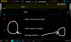
After a more thorough investigation of my 4-deck setup, I think I can now give an explanation of why a multideck setup sounds better (or different) than a 1-deck setup. After carefully setting up testing bit patterns, checking the I2S bus for bit-correctness, I can now feed the DDDAC with a predictable bit pattern / signal. My setup is the following:

One can see that the right channel has no such patterns. These patterns vary as can be seen in the following two closeups:


This stairstep pattern has the following characteristics:
This means that when combining multiple DACs, every DAC will "fire" at a different time, which then leads to the stairstep pattern as can be seen on the left channel. For other setups (4-deck, 8-deck) I'd expect similar patterns, whereas the height of the steps will be different but the length of the stairstep should be the same.
These stairstep patterns can btw. also be seen in other signals, too, e.g. a high-frequency sine and such. For signals with a lower frequency, the steps can only be guessed, moreover it's hard to trigger the signal for these cases.
I assume that such a pattern is audible, which may be the reason why a multideck setup sounds different.
Why this sounds "better" I can't say, but I think that smoothing the wave (via stairsteps) acts similar to a filter and this may be positively perceived.
Anyway, I still have no good explanation of why this happens. Why would a DAC fire at a "random" clock pulse? Unfortunately I don't have a good explanation, it's especially a pity that the data sheet of the 1794 does not contain details about the internals. However, a hint may be the following:
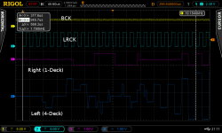
When setting the DSO to single-shot and starting the I2S stream (triggering on LRCK), one can see that the DAC seems to have some kind of setup, which differs for every measurement as shown in the following two screens:


The setup seems to complete after around 24-25 LRCK clocks or after ~ 550µs. After this setup time, the output signal is stable. The same applies to any kind of signal (sine etc.). A silence pattern is, however, also fine for setup. Silence between a square signal does not alter any following signal.
To my mind there seems to be some kind of synchronization or something else going on internally in the DAC, perhaps it's the jitter correction circuit that is somehow locking on to a specific flank of the BCK signal?
I personally would very much like to get feedback from you regarding this topic, especially:
Anyway, many thanks to everyone, I really like the sound of the DDDAC - and it's a lot of fun to tinker around with it to improve the sound even more!
Best Regards
Hermann
Hi DDDAC-Lovers,
After a more thorough investigation of my 4-deck setup, I think I can now give an explanation of why a multideck setup sounds better (or different) than a 1-deck setup. After carefully setting up testing bit patterns, checking the I2S bus for bit-correctness, I can now feed the DDDAC with a predictable bit pattern / signal. My setup is the following:
- A Raspberry Pi as a I2S source
- A square signal with 22,05kHz
- Left channel: all 4 DDDAC decks
- Right channel: Only 1 Deck (I cut the output of the upper decks), so that I can compare the output of the 4-deck with the 1-deck
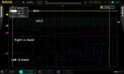
- A DSO, whereas channel 1 is on the I2S BCK, channel 2 either on Data or LRCK, channel 3 on the right channel (1-deck, positive/ground) and channel 4 on the left channel (4-deck, positive/ground)
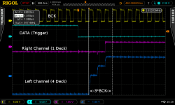
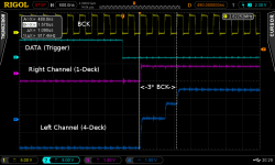
One can see that the right channel has no such patterns. These patterns vary as can be seen in the following two closeups:
This stairstep pattern has the following characteristics:
- The pattern only changes if I disrupt the I2S stream (e.g. by pressing pause/stop or switching from the I2S input to the SPDIF-input and back on the mainboard, otherwise it is stable, so this is no jitter.
- It is always within 3 BCK clock cycles (1.02µs)
- The stairstep can be anything from no steps up to 4 steps, whereas statistically, most often 3 steps seem to occur.
This means that when combining multiple DACs, every DAC will "fire" at a different time, which then leads to the stairstep pattern as can be seen on the left channel. For other setups (4-deck, 8-deck) I'd expect similar patterns, whereas the height of the steps will be different but the length of the stairstep should be the same.
These stairstep patterns can btw. also be seen in other signals, too, e.g. a high-frequency sine and such. For signals with a lower frequency, the steps can only be guessed, moreover it's hard to trigger the signal for these cases.
I assume that such a pattern is audible, which may be the reason why a multideck setup sounds different.
Why this sounds "better" I can't say, but I think that smoothing the wave (via stairsteps) acts similar to a filter and this may be positively perceived.
Anyway, I still have no good explanation of why this happens. Why would a DAC fire at a "random" clock pulse? Unfortunately I don't have a good explanation, it's especially a pity that the data sheet of the 1794 does not contain details about the internals. However, a hint may be the following:
When setting the DSO to single-shot and starting the I2S stream (triggering on LRCK), one can see that the DAC seems to have some kind of setup, which differs for every measurement as shown in the following two screens:
The setup seems to complete after around 24-25 LRCK clocks or after ~ 550µs. After this setup time, the output signal is stable. The same applies to any kind of signal (sine etc.). A silence pattern is, however, also fine for setup. Silence between a square signal does not alter any following signal.
To my mind there seems to be some kind of synchronization or something else going on internally in the DAC, perhaps it's the jitter correction circuit that is somehow locking on to a specific flank of the BCK signal?
I personally would very much like to get feedback from you regarding this topic, especially:
- In case you have a DDDAC + DSO, do you get the same / similar measurement results?
- If you have a multi-deck DSO, could you try to check if pressing pause/play alters the sound signal? I personally assume that different stairstep patterns will also sound different!
Anyway, many thanks to everyone, I really like the sound of the DDDAC - and it's a lot of fun to tinker around with it to improve the sound even more!
Best Regards
Hermann
Attachments
Time to to take electrical safety a bit more seriously and consider yourself lucky that you didn't get mains electricity flowing through your chassis and into something that you care about...
I fully appreciate that sounds a bit preachy, but we're all here for the fun and the music and you can't enjoy much of either if you get too much electrickery into you....
Not preachy mate, your spot on.
I'm building an LDR pre amp and off board PSU, then Im back to my DDDAC, I paln to empty the chasis and start again.
Have you managed to test your unregulated PSU to the DAC boards? Any thoughts?
Hi Doede,
I recently built your dac in a 4-deck set-up, with corresponding dddac PSU and output transformers. And it sounds great.
But now I'm reading all kind of tweaks on this forum and I want to make some serious improvements. Can you give me a short-list of the most significant tweaks in your opinion? It can be brief, there's no need for 'explaining why' or 'how it works'. I can find it on this site.
Thanks,
Hans.
Hi DDDAC-Lovers,
After a more thorough investigation of my 4-deck setup, I think I can now give an explanation of why a multideck setup sounds better (or different) than a 1-deck setup.
This seems quite odd. Assuming thereis no significant skewing of the timing signals going to each of the four DAC chips, it appears that each PCM1794A is converting the same sample data in to differing analog output levels, in some instances, dramatically different. If there simply were a small and constant delay in the data conversion instant among the four DACs, then the summed result would be a form of linear interpolation being performed at the output summing node. However, some of you scope screen photos do not appear to consistantly show that. Instead, the summed output signal often appears to jump from level to level randomly. Obviously, that cannot be the case else the sound would be 100% noise and distortion. Not sure what behavior you have captured with your scope.
Last edited:
Hi Doede,
I recently built your dac in a 4-deck set-up, with corresponding dddac PSU and output transformers. And it sounds great.
But now I'm reading all kind of tweaks on this forum and I want to make some serious improvements. Can you give me a short-list of the most significant tweaks in your opinion? It can be brief, there's no need for 'explaining why' or 'how it works'. I can find it on this site.
Thanks,
Hans.
Please, check Carlsor's http://www.diyaudio.com/forums/digi...-upgraded-single-board-pcm1794-nos-dddac.html
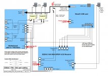
I'm lost here, I connected it like you see in the pic only without the usb boards and both the 1794 DAC board and the 1543 SPDIF board use the same psu but with SPDIF input I get no sound but when I only connect the usb board directly to the DAC in works like a sharm.I have two 1543MK2 SPDIF boards and with both no signal.When I use the switch I hear the relays clicking.
Attachments
This seems quite odd. Assuming thereis no significant skewing of the timing signals going to each of the four DAC chips, it appears that each PCM1794A is converting the same sample data in to differing analog output levels, in some instances, dramatically different. If there simply were a small and constant delay in the data conversion instant among the four DACs, then the summed result would be a form of linear interpolation being performed at the output summing node. However, some of you scope screen photos do not appear to consistantly show that. Instead, the summed output signal often appears to jump from level to level randomly. Obviously, that cannot be the case else the sound would be 100% noise and distortion. Not sure what behavior you have captured with your scope.
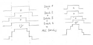
Hi, Thanks for your replay - well, yes, I also doubt that there's a significant skewing of the time signals between the DACs. No, the DACs are not converting the received signals into different analog levels, they just do it at a slightly different time. The following picture shows what seems to happen (two examples, the latter one is the same as the DSO screenshot in my previous post):
So, each DAC does convert the signal to the very same level, but the time it outputs this signal is out of phase by up to 3 BCK clocks. When the result of these displaced signals is added up, the result is a stairstep pattern.
And no, there won't be noise as this phase-shifting is constant for every deck during a constant I2S stream, so this behaviour is different to jitter. If the I2S stream stops (no BCK/LRCK on the I2S, e.g. when the music is stopped) and started again, every DAC locks in to a new phase, thus the pattern is different.
The randomness of this phase-locking seems to come from the setup of the DAC when the I2S stream starts - at least it can be seen that there is some kind of randomness during the setup phase of each DAC whereas I have no clue why / where this comes from and if it's possible to control it in any way.
Best Regards,
Hermann
Attachments
Interesting stuff Hermann,
What was the sample rate of the files you created?
If you keep the square wave frequency the same, but change the sample frequency, how does this effect the behaviour? Are the steps longer with a lower sample frequency?
Have you tried with identical length data/bck/lr wires from the mainboard to each deck and see if the behaviour is the same?
Interesting stuff Hermann,
What was the sample rate of the files you created?
If you keep the square wave frequency the same, but change the sample frequency, how does this effect the behaviour? Are the steps longer with a lower sample frequency?
Have you tried with identical length data/bck/lr wires from the mainboard to each deck and see if the behaviour is the same?
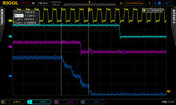
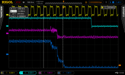
Well, the sample rate of the square wave was 44.1kHz. The following are screenshots of a square wave of 192kHz with the same square wave frequency (22050Hz):
So, one can see the exact same behaviour (the signal is more distorted, the pattern is the same and is stable for a stable I2S stream), but at a higher clock speed as the sampling rate is now 192kHz. The phase of the for decks is randomly distributed over 3 BCK cycles, but as the frequency of BCK is higher (~ 5 times), the stairstep patterns are shorter at 192kHz than for 44.1kHz.
I doubt that the length of the I2S wires to the decks make any difference as one can see that the phase for a single deck also randomly changes within these 3 BCK cycles, although the wire length is of course always the same.
Best Regards,
Hermann
Attachments
hmm, yes.Well, the sample rate of the square wave was 44.1kHz. The following are screenshots of a square wave of 192kHz with the same square wave frequency (22050Hz):
So, one can see the exact same behaviour (the signal is more distorted, the pattern is the same and is stable for a stable I2S stream), but at a higher clock speed as the sampling rate is now 192kHz. The phase of the for decks is randomly distributed over 3 BCK cycles, but as the frequency of BCK is higher (~ 5 times), the stairstep patterns are shorter at 192kHz than for 44.1kHz.
I doubt that the length of the I2S wires to the decks make any difference as one can see that the phase for a single deck also randomly changes within these 3 BCK cycles, although the wire length is of course always the same.
Best Regards,
Hermann
It's as though some high level part of each chip has a variation in start-up time of within a few clock cycles each time it operates. Waking up from the zero detection or the system clock detection circuit locking in to the frequency each time maybe?
So this variation can happen between left and right channels even with 1 deck I guess.
Good point about the wiring length. That never changes does it.
hmm, yes.
It's as though some high level part of each chip has a variation in start-up time of within a few clock cycles each time it operates. Waking up from the zero detection or the system clock detection circuit locking in to the frequency each time maybe?
So this variation can happen between left and right channels even with 1 deck I guess.
Good point about the wiring length. That never changes does it.
Yes, exactly, this also happens between left and right channels. I'm wondering if this waking up from the zero detection can be controlled / synchronized in some way. The DAC does have a reset pin - maybe it could be utilized in some way?
The other idea is: If these stairstep-patterns are perceived as "better" it would be possible to simply delay the I2S signals by some extra clocks via some digital logic between the decks. This way, the stairs would get wider - and maybe the sound gets even better this way?
Best Regards,
Hermann
Have you managed to test your unregulated PSU to the DAC boards? Any thoughts?
Hi James,
Most folk on this Forum are using unregulated psus with their super regs, because they sound better. I went a step further and tested separate digital and analogue psus with the super regs and those sounded better too.
A friend of mine tried unregulated psus of the correct voltage with the stock regulators and he reports an increase in SQ with these over the stock psus. So there you have it. It seems the Dac in standard form or with upgraded regulators responds well-like most digital /analogue devices-to looser (less pre regulated) and bigger psus.
Thanks for that David,
DWjames was going to spend time reconfiguring his unregulated PSU and let us know whut his findings were.
I have ordered the Chokes and they are on their way to me, when they arrive Ill make up the new PSU for the DDDAC, It would be really interesting to pop up to your neck of the woods and see what you have done.
Yes, it would be nice if there was an external way of synching this behaviour, but as you say, it's also possible that this behaviour is part of what makes a multi-deck dddac setup sound like it does.Yes, exactly, this also happens between left and right channels. I'm wondering if this waking up from the zero detection can be controlled / synchronized in some way. The DAC does have a reset pin - maybe it could be utilized in some way?
The other idea is: If these stairstep-patterns are perceived as "better" it would be possible to simply delay the I2S signals by some extra clocks via some digital logic between the decks. This way, the stairs would get wider - and maybe the sound gets even better this way?
Best Regards,
Hermann
I wonder if it reduces the effect of aliases that people report from NOS dacs. I guess it would spread them out? From 44khz source material, the aliases would be around 22khz. Just inside of what our audio equipment will output and our ears can hear.
I note that the new Bottlehead DAC for example is NOS, but with filtering applied separately to apparently give the best of both worlds - Bottlehead DAC | Bottlehead
- Home
- Source & Line
- Digital Line Level
- A NOS 192/24 DAC with the PCM1794 (and WaveIO USB input)