hello friends...
someone please help me to build this amplifier. will it work ? what changes this circuit will need to work on 12 V Supply and substitute for 2N3904 and 2N3906 as i cant find them in my town. i have bc557,558 and bc547,548. can i use MJE3055 instead 2N3055? please help me friends.
here is the link
90 W audio power amplifier based on transistor - Amplifier Circuit
Attachments
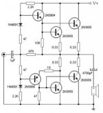
BC557,547, and bc558,548, won't work. This appears to be set up for 120 ma current in the input transistors, and those are 100 ma max parts.
If 500 ma npn and pnp TO92 package parts aren't available, you could probably get away with TO220 or TO125 parts like BD139/140 or TIP31/32. Part gains are much higher these days than when most things were designed. At least the parts from ON semi I am getting. I don't know about the *****ese clone market parts, which operates outside North American and Europe.
There are probably lots of 2sc**** 2sa**** parts that will work, you need Vceo >35, Ic >200 ma, Pd >500 mw which are pretty common specs around the world for TO92 parts. I use MPSA05 and 55 for this sort of thing, although the gains of around 400 are driving me nuts on old design schematics. Also you need more ce (collector emitter) disk capacitors on the drivers and possibly the inputs on fast parts like they make now. (Ft > 1 mhz).
Datasheet conforming MJE3055 should be fine, although many people find clones don't have the SOA of the real parts.
This is going to be rather vile sounding with no crossover elimination parts. I suggest you look at the AX6 for a start, http://www.diyaudio.com/forums/solid-state/236256-retro-amp-50w-single-supply-19.html
but you would have to lower the resistor values on the input and VAS stages to make it work on 12 VDC power supply. You probably don't need an output cap as big as 4700, I find 3300 fine on 8 ohm speakers: Unless you are driving a sub-woofer.
You have to look back towards page one of the link article to find the schematic diagram. He has added a idle current control potentiometer to the layout for those of us that have different gain parts than he used, without updating the schematic diagram.
Don't forget heat sink and isolators on the output transistors, and I usually put bits of aluminum on the driver stage transistors too to eliminate future problems if I turn the amp up.
I build stuff on insulating board like NEMA C laminate 1/16", that I drill holes in, so I don't do circuit boards like the AX6 designer (Mike Slabovik?) offers the patterns for.
Last edited:
Boy, 99.99% of the posters on here really love burning up speakers don't they?What is your power supply?Do you have -/+25v supply?
On a split supply direct connect amp, if you make one stupid bad solder joint PHHHHT!!!, your speaker coil insulation could be cinders.
Somebody building one of these probably hasn't soldered 100 good connections yet.
Output Capacitor amps are best for experiments, IMHO. Armstrong 621, Leak ST70, AX6, etc.Much more stupid proof. I had a ball of fire 6" in diameter when a solder joint pulled loose, no damage occured to my $150 speaker. Hooray for speaker capacitors. If you have a single supply and they never cross zero volts, I can't hear them, either. My hearing rolls off at 14000 hz due to Army service, your results may vary.
BTW, that 1 uf input capacitor on the OP design is a little light these days when 4.7 uf is $.08. Buy the bigger cap for more bass.
Last edited:
I can find bd 139/140. I have 12-0-12 5A power supply. what part should I change in this circuit in order to make it work with 12-0-12. thanks indianajo(nes) and batson.
Was the voltage going into the output capacitor about 6? If not that is a sign something is unbalenced somewhere. 1/2 rail voltage is the desired operation point for the midpoint of the output transistors.
Did your BC548/558 get hot? Bad connections are quite common when you are starting out. Use a DVM and look for impossible voltages - ends of the wire different voltages on the component leads, Vbe not 0.6 v , Vce not between 2 and 2/3 rail voltage, wrong polarity etc.
You can increase the 100 ohms to 220 and also the 47 ohm, and maybe series the + and - 12 supply to make 24 single rail supply.
You'll need a high drive source like a CD player or transistor radio to use the actual circuit since it doesn't have a high gain input transistor. It doesn't have any global feedback either, which makes the sound rather primitive. The AX6 is a much better design. If you do have a split supply, you can fool with the power to the input transistor with the center tap to stabilize the operating point of the input transistor, without actually running the output transistor direct connect in the speaker toasting configuration. I'm working with a transformer with no center tap, so I don't have an actual design.
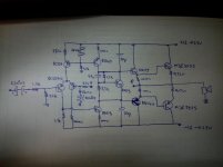
Here is a better circuit. You can omit a pair of output transistors if you like.
An externally hosted image should be here but it was not working when we last tested it.
Thats why u measure output first.Then you connect speakers.Boy, 99.99% of the posters on here really love burning up speakers don't they?
On a split supply direct connect amp, if you make one stupid bad solder joint PHHHHT!!!, your speaker coil insulation could be cinders.
Somebody building one of these probably hasn't soldered 100 good connections yet.
Output Capacitor amps are best for experiments, IMHO. Armstrong 621, Leak ST70, AX6, etc.Much more stupid proof. I had a ball of fire 6" in diameter when a solder joint pulled loose, no damage occured to my $150 speaker. Hooray for speaker capacitors. If you have a single supply and they never cross zero volts, I can't hear them, either. My hearing rolls off at 14000 hz due to Army service, your results may vary.
BTW, that 1 uf input capacitor on the OP design is a little light these days when 4.7 uf is $.08. Buy the bigger cap for more bass.
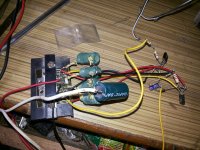
with bd 139/140 its working... there is humming sound and output is very low.. In fact humming is louder than the sound.. what next.. its on 0-24 (12-0-12 series) supply. output is less then my cell phone external speaker.... how to modify it to work with at least 24V. thanks to all of you...

now output transistor are getting hot.. humming is there.. very low output.. bd139/140 not even getting warm..
The circuit you have chosen has no voltage gain . The volume you get out will be approx what you put in . It would be better described as a buffer . The excessive hum you are getting is because you have not used full wave rectification on your power supply and the smoothing capacitor value looks minimal . Choose a better circuit and start again .
Forget this circuit.Dont waste your time.I gave you tested circuit.You will like it and it is simple.But you cant do circuit on air,it better use at least board so there will be no short circuit.hello friends...
someone please help me to build this amplifier. will it work ? what changes this circuit will need to work on 12 V Supply and substitute for 2N3904 and 2N3906 as i cant find them in my town. i have bc557,558 and bc547,548. can i use MJE3055 instead 2N3055? please help me friends.
here is the link
90 W audio power amplifier based on transistor - Amplifier Circuit
- Home
- Amplifiers
- Solid State
- help me building this 2N3055 amplifier