whats those 2 diode value and I don't have 2955. can you modify this with only 3055. and any possible substitute for bd139/140. thanks.
Have you looked at the AX6 link? down towards page 1 etc? It has a pnp input stage and a VAS (voltage amplifier) which your output section is missing.
your original circuit looks like any single supply amp output stage, without the voltage gain stage, input stage, and feedback. Also is missing the bias current control circuit to control crossover distortion versus heat in the output transistors. I like about 20 ma idle current.
The AX6 has a pot to control idle current. If you prefer a transistor mounted on the OT heat sink which is more temperature stable, the Ron Ellis Basic 50 is the ticket. About like nigel's circuit, but single supply instead of speaker burner direct connect. (http://www.diyaudio.com/forums/solid-state/185843-basic-50w-hifi-amp-beginners.html)
As far as the Batson's objection that he measures the DC out before connecting the speaker, my solder joint melted after a 3 1/2 hour rehearsal, causing the ball of fire, burnt output transistors and some other burnt parts (but no speaker damage due to the cap.)
Both AX6 and Basic 50 are quasi-comp which means all 2n3055/mje3055 output transistors.
If you can't find the 2.7 v zener diode in the basic 50, you can stack up 4 regular diodes instead. The rest of the parts are ones you've got. Forget the 10000 uf output capacitor, 4700 ohms is way enough for a 8 ohm or 4 ohm speaker IMHO.
If you can stack up (series connect) the output windings of two of those 24 VAC doorbell/furnace control transformers, you'd have 48 vAC rms or about 70v peak, which is getting right to the range of 63 vdc the AX6 and Basic 50 are designed for. You'd need 63 or 80 v rated main caps of course, and some of the internal caps need to go that high.
Last edited:
ax6 yes.. I don't have output transistors... how xan I use 3055. and I don't have 2955. if series transformer will work I have extra transformers.
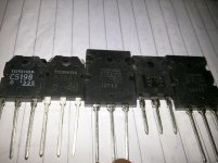
whats the substitute for 2n3773 and 2sc4793 and 2sa1837 as I don't have them. I have couple of TTC5200, TTA1943, irfp250n, A1941, C5198 and Z44 mosfet, bd139, bd140, bc548, bc558, 5401, s9015, s9014, 5551, a1013, a1015 etc
Your MJE3055 are the output transistors.
Your original schematic has the two drivers (now bd139/140) and the two output transistors of the AX6 or basic 50.
What your original schematic is missing is the input stage, the feedback, the VAS, and the output transistor bias idle current control.
The original schematic has an extra pair of 2n3055 (mje3055) inbetween the drivers (bd139/140) and the output 2n3055, which are kind of redundant at these power levels with a 24 v supply. You can get 50-60 watts out of a pair of mje3055, with peaks of higher current than that with a 70 v supply. Just your RMS (full time) power is limited by the heat sink and the SOA limit of the parts. In my circuit I'm aiming for 200 w cannon shots in 1812 overture, with a single pair of output transistors, although my average PA volume will be about 10 watts on keyboard. A bass guitar amp, by contrast, needs 4 output transistors because the volume is the same all the time.
Last edited:
Ofcourse i will help you.but first make a dicision what you really want.thats good if you have 5200/1943 and 2sc4793 and 2sa1837.you can get really good amp from them.but you need more serious transformer.You can use 5200/1943 instead 2n3055 and they are much better .
12-0-12 is ok but not enough.When you are ready tell me compnents then i will send new cicuit.
2n5401/2n5551 and TTC5200/TTA1493 and 2sc4793/2sa1837 are best and cheapest transistors for amp.How many you have them?
12-0-12 is ok but not enough.When you are ready tell me compnents then i will send new cicuit.
2n5401/2n5551 and TTC5200/TTA1493 and 2sc4793/2sa1837 are best and cheapest transistors for amp.How many you have them?
Last edited:
I presume you are a newbie in amp making. forget the first 3055 circuit. that is nothing but trash. with a single 12V supply, the max output you can get is around 5-7W. find some good split supply stuff. TTC5200/TTA1493 is a good output pair. remember, for more output power you always require more voltage and more pairs of output transistors. again, a good layout is a must for hum free distortion free working of amps. do some reserch in the net and have fun making amps.
If accident is coming then there is no way to run 🙂 Use cap or dont use it doesnt matter.We learn better when we do mistake.Because you never forget it again.Have you looked at the AX6 link? down towards page 1 etc? It has a pnp input stage and a VAS (voltage amplifier) which your output section is missing.
your original circuit looks like any single supply amp output stage, without the voltage gain stage, input stage, and feedback. Also is missing the bias current control circuit to control crossover distortion versus heat in the output transistors. I like about 20 ma idle current.
The AX6 has a pot to control idle current. If you prefer a transistor mounted on the OT heat sink which is more temperature stable, the Ron Ellis Basic 50 is the ticket. About like nigel's circuit, but single supply instead of speaker burner direct connect. (http://www.diyaudio.com/forums/solid-state/185843-basic-50w-hifi-amp-beginners.html)
As far as the Batson's objection that he measures the DC out before connecting the speaker, my solder joint melted after a 3 1/2 hour rehearsal, causing the ball of fire, burnt output transistors and some other burnt parts (but no speaker damage due to the cap.)
Both AX6 and Basic 50 are quasi-comp which means all 2n3055/mje3055 output transistors.
If you can't find the 2.7 v zener diode in the basic 50, you can stack up 4 regular diodes instead. The rest of the parts are ones you've got. Forget the 10000 uf output capacitor, 4700 ohms is way enough for a 8 ohm or 4 ohm speaker IMHO.
If you can stack up (series connect) the output windings of two of those 24 VAC doorbell/furnace control transformers, you'd have 48 vAC rms or about 70v peak, which is getting right to the range of 63 vdc the AX6 and Basic 50 are designed for. You'd need 63 or 80 v rated main caps of course, and some of the internal caps need to go that high.
I can learn as well from a $6 mistake (no fans, solder melted) as a $156 mistake (speaker is fried). In fact I learn faster because I don't have to wait three months to save up the $150 for another speaker. Much less the cost of renting a truck to get another used PA speaker home. Equivalent new PA speaker, $600 plus freight from out of town.If accident is coming then there is no way to run 🙂 Use cap or dont use it doesnt matter.We learn better when we do mistake.Because you never forget it again.
hello friends after attending 4 wedding parties I am here again.. will soon update which project I am going to start.. hopefully ax6...
nice blog.. will go through it..
Can you tell me more about this amplifier? Fixed bias so not much flexibility.Here one of my circuits that i tested many times in many versions.It is very simple and powerfull.You can use your bc557,BD139,140 and MJE3055/2955
and with +/-12 volts you will get enough 🙂 Good luck
Batson said “many versions”. I’ll bet one or two of them had a pot in place of that 3.3k resistor in the bias network so it can be adjusted. It’s not rocket science.
There is one thing that is WRONG with it. The BD140 current source needs a ~1k base stopper resistor. If this is omitted the amplifier can latch to the rail when clipping (Sending DC to the speakers). When built as drawn, sometimes you get lucky and it behaves “normally” when clipping, other times it does not. It is heavily dependent on the exact components chosen. When I build one like this, I use separate diode/resistor bias for each of the two current sources. It’s only a couple extra very cheap components and it ensures that one current source cannot upset the other when dropping out of voltage compliance. If you cannot afford (or can’t scavenge) two extra 1N4148 diodes you’re in the wrong hobby.
There is one thing that is WRONG with it. The BD140 current source needs a ~1k base stopper resistor. If this is omitted the amplifier can latch to the rail when clipping (Sending DC to the speakers). When built as drawn, sometimes you get lucky and it behaves “normally” when clipping, other times it does not. It is heavily dependent on the exact components chosen. When I build one like this, I use separate diode/resistor bias for each of the two current sources. It’s only a couple extra very cheap components and it ensures that one current source cannot upset the other when dropping out of voltage compliance. If you cannot afford (or can’t scavenge) two extra 1N4148 diodes you’re in the wrong hobby.

- Home
- Amplifiers
- Solid State
- help me building this 2N3055 amplifier