Hey all. I compiled the noise measurements from this thread so far. I may have missed some, and not all the measurements were made on all transistors.
Code:
BJT noise measured by Richard Marsh

Q		Hfe	Ic	Vce	10Hz	100Hz	1KHz	10KHz	100KHz	Rb

BC337		700@5mA	3mA	15V		3.5nV	0.6nV	0.65nV	0.53nV	17.4
BC327		407@5mA	3mA	15V	5nV	0.7nV	0.5nV	0.55nV	0.55nV	10.8

BC550C										167
BC560C			3mA	15V	3nV	2.5nV	1.6nV	1.6nV	1.6nV?	170

2N4401		170@5mA	1mA	15V	1.5nV	0.9nV	0.65nV	0.65nV	0.8nV	38
			3mA	15V	4.5nV	1.3nV	0.6nV	0.6nV	1.3nV	38
2N4403										40

2N5087		460@5mA	100uA	15V	2.5nV	3.2nV	1.4nV	1.5nV	1.3nV
		460@5mA	3mA	15V	2.2nV	4nV	0.8nV	0.7nV	0.75nV

2N2907A		280@5mA	3mA	15V	6nV	2.4nV	0.95nV	0.75nV	0.75nV
2N2219A

2SA970			3mA	15V		4.5nV	1.1nV	0.9nV	1nV	25
2SC2240GR	330@5mA	3mA	15V?	2nV	2.8nV	0.7nV	0.65nV	0.6nV	39

2SB737			3mA	15V		4.2nV	0.35nV	0.5nV	0.3nV

2N2222

MPSA18										900?

NOS:
2N2484A			3mA	15V	40nV	12nV	4nV	2.6nV	2.4nV
2N2222A		133@5mA	1mA	15V	3nV	1.2nV	0.9nV	0.85nV	1nV
3mA 15V 4.5nV 3.3nV 0.9nV 1nV 0.9nVHas anyone built the Wurer or KPeter (linuxguru) with real parts and bench tested it? Thanks , G.R.
Has anyone built the Wurer or KPeter (linuxguru) with real parts and bench tested it? Thanks , G.R.
Ken Peter Schottky-switched Class-AB buffer: not yet built, still in simulation (on again, off again - no pun intended). It looks good, but requires careful matching of a BJT Vbe to 2x Vf of the schottkys, and quiescent current may be a bit twitchy (depends on ambient temps).
My attention was diverted by some full-range speaker builds, so I'll get back to this in a month or so.
Thanks! Why can't it be biased full Class A? 1 volt peak to peak output will drive most power amps to clipping. It certainly should do that in Class A. You used 2n4416 as current sink. Is the 2n4416A OK? I have them on hand. Thanks G.R.
Thanks! Why can't it be biased full Class A? 1 volt peak to peak output will drive most power amps to clipping. It certainly should do that in Class A. You used 2n4416 as current sink. Is the 2n4416A OK? I have them on hand. Thanks G.R.
Ken Peter's output stage will also work in Class-A, for sure, but it wouldn't really be required because crossover distortion is not an issue there. In fact, fior normal line-level loads of (say) 10k and above, it will effectively be running in Class-A anyway.
You can use almost any JFET with Idss > ~2.5 mA as the LTP current source, as long as you adjust the source resistance to make the LTP tail current about 2 mA (1 mA though each leg). Even that's not critical - if you lower the tail current, it will still work, but with lower GBW and higher THD.
Thanks! Why can't it be biased full Class A? 1 volt peak to peak output will drive most power amps to clipping...
BTW, there's another Class-A buffer with very low distortion that's been on my back-burner for a few years - the Cantilevered Cascode Buffer. The latest variant is just a random find of mine about a month ago:
http://www.diyaudio.com/forums/anal...buffer-ccb-aka-linuxbuffer-2.html#post4162273
Its claim to fame is that it produces predominantly 2nd/even-harmonic distortion.
Suppressing the odd, 3rd and 5th is a very good idea. I believe that most of the unpleasant distortions reside there. Thanks, G.R.

* Bump *
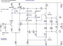
Just woke up from a long period of hibernation and came up with the following update to the Melcor 1731 topology. It's not the same schematic as the original, but is derived from it and has several key improvements to the classic Melcor 1731:
1. Uses a current mirror to load the LTP collectors, which gives a more useful input voltage swing for things like voltage followers and so on (the original used plain 39k resistors as the collector load).
2. The VAS is greatly modified to use the cascode structure from SWOPA. IMHO, this is a critical update to lower THD20 as well as maintain a favourable distortion profile with dominant H2.
3. Numerous biasing changes to reduce VAS and output stage quiescent current, while allowing operation over an extended +/- 6V to +/-18V rails, which is more practical for DIP footprints.
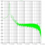
It's still work in progress, and some minor biasing changes as well as compensation tweaks are possible. However, it is unity-gain stable with the component values shown. The simulated THD20 at 4V amplitude into 600R is ~ -110 dBR with H2 dominant, and H3 is a further -12 dB below.
The crux of the low BJT count is the elaborate LTP current mirror that re-purposes existing Q5 as a voltage-follower/buffer, and also biases/drives the VAS cascode Q7. IIRC, this is the lowest-distortion Class-AB discrete opamp with only 11 BJTs that I've worked on in the last ~8 years or so. As shown, it will drive low-Z headphone loads also.
Just woke up from a long period of hibernation and came up with the following update to the Melcor 1731 topology. It's not the same schematic as the original, but is derived from it and has several key improvements to the classic Melcor 1731:
1. Uses a current mirror to load the LTP collectors, which gives a more useful input voltage swing for things like voltage followers and so on (the original used plain 39k resistors as the collector load).
2. The VAS is greatly modified to use the cascode structure from SWOPA. IMHO, this is a critical update to lower THD20 as well as maintain a favourable distortion profile with dominant H2.
3. Numerous biasing changes to reduce VAS and output stage quiescent current, while allowing operation over an extended +/- 6V to +/-18V rails, which is more practical for DIP footprints.
It's still work in progress, and some minor biasing changes as well as compensation tweaks are possible. However, it is unity-gain stable with the component values shown. The simulated THD20 at 4V amplitude into 600R is ~ -110 dBR with H2 dominant, and H3 is a further -12 dB below.
The crux of the low BJT count is the elaborate LTP current mirror that re-purposes existing Q5 as a voltage-follower/buffer, and also biases/drives the VAS cascode Q7. IIRC, this is the lowest-distortion Class-AB discrete opamp with only 11 BJTs that I've worked on in the last ~8 years or so. As shown, it will drive low-Z headphone loads also.
Attachments
Why can't it be extended to use +&-24v rails? Have you built it with real parts and tested it on a bench? Have you used it as a follower with the + input grounded and 100% feedback? Thanks Ray
Why can't it be extended to use +&-24v rails? Have you built it with real parts and tested it on a bench? Have you used it as a follower with the + input grounded and 100% feedback? Thanks Ray
It's not often that one encounters +/- 24V rails in equipment with DIP8 duals, which is what I'm aiming this design at. The limitation is mainly the Vceo rating of SMD VAS and driver-stage transistors - commodity BC8xx parts top out at around 65V, which is probably sufficient for +/- 24V rails. I'd probably check and re-check the power dissipation limits as well - the driver stage runs with an Icq of ~2 mA. If it's only going to be used for say +/- 18 to 24V rails, the driver stage can be re-biased for lower Icq in the region of 1 mA.
I have a mostly-SMD layout completed for BC8xx parts and BC639/640 outputs. It looks to be error-free and feasible to fabricate and prototype, but I can't provide a timeline on when that might happen. I'd prefer to check and recheck the layout for at least a week before sending out the Gerbers. Prototype testing will happen only after PCB turn-around and hand-assembly.
An inverting voltage-shunt configuration should work and is usually easier to stabilize than a non-inverting unity-gain voltage follower as simulated above. The topology is derived from a 50+ year old proven design, so it will probably work first-shot. The only issue is compensation/stability in the real world, which is always work in progress.
Last edited:
If there's interest in the LM394 for this project (it was used in the Jensen 990 until National/TI dropped it), there's a coompany that's making it again:
Matched NPN transistor pair
Matched NPN transistor pair
Can CMOS be replicated in a DIY opamp?
I want to design an opamp with the goals of low input bias, high PSRR, and reasonable slew rate in that order. As far as I know CMOS technology is the only thing that can achieve Fa of input bias current. Can it be replicated with discreet components?
I want to design an opamp with the goals of low input bias, high PSRR, and reasonable slew rate in that order. As far as I know CMOS technology is the only thing that can achieve Fa of input bias current. Can it be replicated with discreet components?
Very few discrete transistors are sold with a datasheet guarantee of femtoampere level gate leakage current. You'd probably have to screen for that yourself which means: you're now in the femtoampere testing business.
- Home
- Source & Line
- Analog Line Level
- Discrete Opamp Open Design