.you can write Ib as a function Vbe.
No you can't. Typical betas on commodity devices can vary 50-400 or more for the same device. For example the collector current at a given Vbe for the same devices could all be the same while the base current would vary 8-1 or more. Ib is simply to the first order the recombination in the base, make it thin enough (super-beta) and beta can reach 4000.
I don't know if you misinterpreted something you read or are just making it up.
"make it thin enough (super-beta)"
Strong memory of my first job in Plessey Semiconductors, 1962. Acid etch silicon npn transistor line licensed from Philco Ford.
The DUT was in a simple DC circuit with an analog meter showing Ib. Pump the acid jet into the base and watch the meter fall. Try and catch it before the acid etched all the way through and you could get a beta in the 100s! Seconds too late and it was scrap!
No feedback, no automation apart from mechanical timers, and the slightest hiccup sprayed acid all over everything!
"make it thin enough (super-beta)"
Try and catch it before the acid etched all the way through and you could get a beta in the 100s! Seconds too late and it was scrap!
Craftsmanship 😉
Nope, 🙂. It is the voltage potential between the base and emitter regions of the semiconductor material which causes the movement of the charge carriers; the emitter, strangely enough 😀, "emits" electrons (for npn) from its heavily doped region into the base region and most of these are "collected" by the collector, under the influence of the voltage potential applied there, to form the collector current. The "leftover" base current that occurs is a function of the geometry and variations in the manufacture of the device - which is why the values of hFE are all over the place, for a particular device number.
Agreed.😀
Base current is not the "left over current".Number of electrons emitted from heavily doped emitter to lightly doped base is much more than that of holes present in base.So the base current by combining electrons and holes present in base region is very small and the "left over" electrons are collected by collector by the influence of collector voltage. If it is on the otherway collector current have much more influence by collector-emitter voltage.That is not happening.
Anyway the most important thing is.....................
.
.
.
.
.
You are the winner of the match😀😀😀😀😀 ha ha ha
I am convinced.🙂🙂🙂
Bigun,I lost all my energy.Some water please.🙂
Thanks to all
BR
Joshvi
Guyz
Can I feed front end of amplifier with +\- 70V and output stage to, without changing any value? Or I need to increase front end current, like changing R5 3k, because front will have something about 0,8mA
Can I feed front end of amplifier with +\- 70V and output stage to, without changing any value? Or I need to increase front end current, like changing R5 3k, because front will have something about 0,8mA
I am convinced.🙂🙂🙂
Bigun,I lost all my energy.Some water please.🙂
Awright everyone, open it up a bit! - give this man some huggin' room ...
Cool, now we can move all these unrelated posts to recycle bin and keep the thread for the very best amplifier NagysAudio has ever heard 😀
Agree .... 😉Cool, now we can move all these unrelated posts to recycle bin and keep the thread for the very best amplifier NagysAudio has ever heard 😀
Attachments
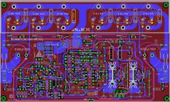
Alexstill separates the +ve rail from the -ve rail and loops the power ground around the outside of the PCB.
Alex,
Did you incorporate all the changes mentioned? So I can make a BOM for everyone with Mouser/RS/Farnell and Ebay part numbers? I will be happy to do that for all who need it. Need it for myself anyway.
Sjoerd
Did you incorporate all the changes mentioned? So I can make a BOM for everyone with Mouser/RS/Farnell and Ebay part numbers? I will be happy to do that for all who need it. Need it for myself anyway.
Sjoerd
Craftsmanship 😉
In my previous job I was a a Product Line GM working in a business that made power mosfets, and at one stage, power mosfets with integrated protection for the auto industry. I used to berate the design team because of the number of development re-spins and accused them of producing 'hand crafted masterpieces'. I was not flavor of the month with them. Funny thing, it was in the UK as well . . . 😀
Agree .... 😉
This is not Goldmund 9.2 , I think it's Goldmund 390 🙂
Regards!


 merry CHRISTmass to you all
 I'm currently trying to begin this project but after hours of reading the entire thing seems to be a complete jumbled mess totally lacking cohesion. Any attempts to render this by members seem to be gleefully ignored and no one can keep track of what changes are being done where or what working versions exist.
It would be very helpful to everyone if any thread veterans could start a clean thread outlining basic information and the various revisions. A basic FAQ section which be useful and should clean up the thread.
Regards.
It would be very helpful to everyone if any thread veterans could start a clean thread outlining basic information and the various revisions. A basic FAQ section which be useful and should clean up the thread.
Regards.
Hello matt09 , the same happened to me, I have a complete box full of parts almost 95% of the materials, but my experience is that nobody in this thread could give precision in so many needed details. It seems to be like some kind of private conversation between the ones that could make this amp work. Hard to get a neat explanation, just warm tips here and there.
Let me tell you that I bought 2 PCB's from the original post from NagysAudio. This guy has been banned for some reason I still can't understand. He received a massive attack of a group of members that never wanted to hear his explanations and he was treated all the time as a lier (¿?). He defended his position that the amplifier worked with the original circuit, but for members like me that started the thread from scratch and tried to listen to every single indication, it was very disappointing the unjustified way in which NagysAudio was treated. At some point he quitted.
After this, the same original project was reproduced with many alterations, new PCB's, circuit revisions and finally some guys showed finished equipment that they never documented neatly.
I uploaded a copy of a schematic trying to contribute some order motion, and except for Liliya and oiphy, nobody replied or helped. The information was still very unreliable considering that my original boards didn't match the final project done here.
http://www.diyaudio.com/forums/soli...lifier-i-have-ever-heard-226.html#post3407019
I have 35 years experience in electronics, I am an educator myself, but I feel this project still unreliable in many ways because of the way it was born and altered. Some day I will sit down and make it work but I would have been much easier with some detailed help from those who could make it work.
Kind regards
DIYAudio has a Wiki section that would be ideal for documenting how to construct this amplifier, and delineating the various PCBs/schematics and incarnations.
If you have a PCB and the schematic that goes with it, then people here can surely help you finish it. And at the same time, the information could be written into the Wiki so that it doesn't get buried with everything else.
If you have a PCB and the schematic that goes with it, then people here can surely help you finish it. And at the same time, the information could be written into the Wiki so that it doesn't get buried with everything else.
I was starting to building this amplifier many times, and i made my variation, different vas transistors and driver too. Schematic of NagysAudio is correct, but we have some oscilations, or mayby I'v got it only 🙂
Changing base resistor on mosfets to higher, N-chanel 330ohm and P-chanel 220ohm, solves oscilations.
Changing base resistor on mosfets to higher, N-chanel 330ohm and P-chanel 220ohm, solves oscilations.
Thank you keantoken and Machina.
OK, I kindly invite those members who would like to contribute to use the Wiki to order this thread. We could start with the original board and then propose all modifications. Dear Machina, YES I can see that oscillations can exist, and NagysAudio originally adviced about this and he included some small capacitors here and there, but I don't see a problem in increasing gate resistors for a test provided this doesn't affect final performance.
The problem is that the suggestions and changes should be precise, well explained and also documented. Sometimes it is not enough to speak. It leads to confusion and errors.
For me, most of the problem is in the protection circuit. I have only a hand written schematic from the original NagysAudio set of schematics. I bought the boards and it came with a set of neat schematics except for the protection circuit.
When I uploaded a complete schematic of this section to compare it with other members I had almost no reply. I would like to know if this circuit is correct or not and if it fits the board traces.
So, would you like to help me ? Could we give it another try ?
How this Wiki works please ?
Thank you in advance
Roberto
- Home
- Amplifiers
- Solid State
- The Very Best Amplifier I Have Ever Heard!!!!