I meant to ask-anyone have any good methods of measuring an amp's quality (In terms of accuracy, realistic sound production, etc) apart from listening to it? I've kind of relied on the scope and the amp's reproduction of square waves so far but I'd like to go farther. I've sort of messed around with the FFT function on my scope, but in all honesty, I'm not 100% sure how to read it; even my instructor said "I'm not sure, focus on your schoolwork". OK, fair enough. Any hints/ideas/tricks out there?

I meant to ask-anyone have any good methods of measuring an amp's quality (In terms of accuracy, realistic sound production, etc) apart from listening to it?
Consider loading this free program (ARTA) up on your windows PC. It uses your PC sound card as an analysis tool. A sound card will usually have at least 16 bits of resolution while a lot of scopes are just 8 bit (vertical resolution).
If you want to throw a bit of money at it, consider one of these which is really just a sound card in a box with proprietary software. But it adds a calibration function which makes absolute measurements easier. Here is a forum thread with a bunch of information.
The problem with PC sound cards, or the QA400, is noise floor. Some sound cards are better than others. The one in the QA400 is pretty good. Specialty analyzers with lower noise floors add another zero or two to the the price tag. 🙂
Last edited:
Amplifier sound quality (its subjective appeal) is a topic full of controversy and debate where playing a numbers game doesn't always equate to top sound quality.
You need to listen to amps that produce different types of distortion spectrum and ask yourself honestly which you prefer listening to. There are no right and wrong answers.
You need to listen to amps that produce different types of distortion spectrum and ask yourself honestly which you prefer listening to. There are no right and wrong answers.
^^^ What Mooly said. 🙂 The equipment can quantify what certain aspects of the signal are doing, but "quality" is really up to the ears.
Amplifier sound quality (its subjective appeal) is a topic full of controversy and debate where playing a numbers game doesn't always equate to top sound quality.
You need to listen to amps that produce different types of distortion spectrum and ask yourself honestly which you prefer listening to. There are no right and wrong answers.
I totally agree-so long as the amp isn't passing along DC or some frequency I can't hear that's frying my headphones. I love the way it's turned out and it's now my main headphone amp (my previous favorite was my O2, but I like mine more!) but I'd just like some empircal data to know WHY I prefer it.
adgr, thanks for the links! I'll definitely be giving the ARTA software a go, and my birthday and christmas are only a couple weeks apart, so maybe I could convince the wife to spring for the QA400. It'll take some thought, however, if I really want to spend so much on just one very specialized tool. One limiting factor is that I have a crappy soundcard and always use my ODAC to listen to anything from my computer.
Last edited:
What kind of "crappy soundcard" would that be? If you've got a Realtek chip with Realtek Windows drivers from 2011/12 you should probably update those (they contained a bug hitting 44.1 kHz, and 24/44 in particular, which resulted in the hardware being set up all wrong), and if you notice a big difference in quality between WASAPI output in exclusive mode and things coming out in shared mode, speakers may be set up with the "full range" option unticked (common in notebooks). Finally, even though relatively few applications use the old MME sound API these days, one should have Windows 7 hotfix KB2653312 installed for those that do.
All that being said, onboard audio typically still doesn't measure that well on the recording side - it tends to get the job done for some vinyl rips at 96 kHz and whatever else people normally do with it, but hardly lends itself to serious measurements.
The thrifty meas-o-phile can get away with relatively little as long as some pitfalls are noted and avoided. For an inexpensive, good unbalanced input recording card, I would look at a Xonar D1, or its DX PCIe cousin. Looks like it's good for about 1.4 Vrms at low distortion (<0.001%) and a dynamic range in excess of 110 dB. (Obviously its bigger brother D2/D2X is even better.) RMAA, while it may have its quirks (like buggy IMD calculation), still makes fairly useful measurement software, too.
One important issue that needs to be taken care of is the big fat ground loop that is being created once connecting a DUT between the output and input of a sound card - professional audio analyzers have galvanically isolated ins and outs for good reason. As long as said DUT does not invariably tie signal ground to safety earth (without a ground lift option), this can be circumvented by going for a balanced input as in the linked article... or just interrupting said ground loop somewhere in the cabling, making things star-grounded again.
Another four things that tend to come in handy:
1. Dummy loads, for measurements under semi-realistic output loading conditions.
2. Resistive attenuators, so you can measure e.g. distortion at levels beyond what the input will normally accept. If, for example, you need to get 7 Vrms down to 1.4 Vrms, I'd give something like 1.8k : 390R (metal film) a shot.
3. A fancy multimeter (preferably TrueRMS) for some absolute level calibration.
4. A low-noise preamplifier, for a better look at output noise levels (best evaluated with DUT inputs shorted). A 2x9V-powered NJM2068 or 2xNJM5534 at 40 dB of gain should be ample.
Last edited:
What kind of "crappy soundcard" would that be? If you've got a Realtek chip with Realtek Windows drivers from 2011/12 you should probably update those (they contained a bug hitting 44.1 kHz, and 24/44 in particular, which resulted in the hardware being set up all wrong), and if you notice a big difference in quality between WASAPI output in exclusive mode and things coming out in shared mode, speakers may be set up with the "full range" option unticked (common in notebooks). Finally, even though relatively few applications use the old MME sound API these days, one should have Windows 7 hotfix KB2653312 installed for those that do.
Another four things that tend to come in handy:
1. Dummy loads, for measurements under semi-realistic output loading conditions.
2. Resistive attenuators, so you can measure e.g. distortion at levels beyond what the input will normally accept. If, for example, you need to get 7 Vrms down to 1.4 Vrms, I'd give something like 1.8k : 390R (metal film) a shot.
3. A fancy multimeter (preferably TrueRMS) for some absolute level calibration.
4. A low-noise preamplifier, for a better look at output noise levels (best evaluated with DUT inputs shorted). A 2x9V-powered NJM2068 or 2xNJM5534 at 40 dB of gain should be ample.
Thanks for the in-depth response, I appreciate it!
I guess it's not so much as a quality issue with the card, it's the fact that it's partially broken; both the output and input jacks were broken a while back, and I only have a laptop so I can't pull it out and replace it. I do have a Creative X-Fi USB that supports recording and output, I'll give it a shot with that, although I really don't like how it colors the sound.
As for the others,
1. Dummy load-check. I've gotten quite a few power resistors that I've been using. They are Dale 1% in 8Ω/35W, 20Ω/25W, 40Ω/100W, 60Ω/15W, 72Ω/25W, 100Ω/25W, 240Ω/15W, 600Ω/10W and a few others I can't remember.
2. Definitely will give that a go!
3. "Fancy" DMM: Check-Fluke 189 & Agilent U1241A
4. Definitely will try that too!
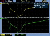
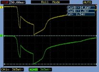
A problem surfaced today-when turning off the amp after listening for about 45 minutes this morning, I heard a very loud thump. I was at school studying, and needed a break, so I went up to the lab and hooked it up to a scope. It's never done this before, but now it's 100% repeatable. I'm guessing it's the voltage regulators being confused by the discharging 1000uF caps, the output 220uF flowing back into the regulators, or the on/off switch is bouncing, or maybe all three, or maybe none of these 🙁 . I've uploaded a few screenshots of what's going on.
Attachments


Last edited:
Bit strange when it starts behaving differently to how it did originally. If you had said it always generated a thump then I would have said that was pretty normal tbh, that it didn't, well you got lucky.
Headphones are super sensitive and so it doesn't take much voltage wise to cause a loud noise. The problems occur as the rails collapse unequally causing a point to be reached where the semiconductors literally drop out of conduction and the circuit no longer obeys the rules... result... the output assumes some small DC voltage and discharges the residual rail charge into the load.
If it never did this before then at least do a basic check and make sure the regs are still working correctly with regard to voltage out. You have to do that just to be sure. If that's OK then I'm not so sure there is much you can do without the added complication of a simple mute circuit on the output.
I agree, I thought it was odd that it just suddenly appeared. I checked for it when the amp was new-It's something I've always been paranoid about. The first amp I built was a Cmoy constructed on perfboard with a simple resistive voltage divider power supply, and the first time I used it, it thumped very hard and it destroyed my Ety ER4s. I kind of wish I'd kept it so I could measure how big the thump was so I could compare it with what happened today, but I remember it sounding louder than what happened today.
I'm thinking now the regulators are damaged in some way. I'm also thinking the shutdown pins on the regs might be part of the problem too, given that the voltage shoots up again briefly after turning it off. I'll have to wait until I go home to really check into it, especially since I'm supposed to be studying all day today.
I'm thinking now the regulators are damaged in some way. I'm also thinking the shutdown pins on the regs might be part of the problem too, given that the voltage shoots up again briefly after turning it off. I'll have to wait until I go home to really check into it, especially since I'm supposed to be studying all day today.
I'm afraid I can't really suggest much else at this stage... and you need to measure and confirm its all basically OK first. As you seem to have access to some pretty decent test gear you could try scopeing both rails and try and see if they decay reasonably equally.
Well, as I expected, the regulators were toast. They measured 18.42V for the LT1963, and -19.34V for the LT3015. I'm surprised the opamps & buffers didn't get harmed. I'm pretty sure they reason they failed is that they were handling too much voltage-the transformer I'd been using put out 22V-CT-22V, so after rectification & smoothing probably something like 27-30VDC. That meant each regulator was dropping ~12-15V(!). I did notice every time I used it that the regulators were very warm.
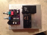
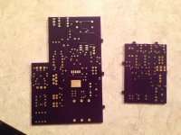
Anyway, I have good news to report! My PCBs came, and I've assembled most of them. I sent out designs for both the full-size version and the portable size. Like I mentioned earlier, I used oshpark.com for them, and I'm very pleased with their service-the PCBs are exactly as I'd designed them, high quality, very quick, and awesome customer service.
Unfortunately I can't actually use either yet since I'm waiting for a more appropriate transformer (will put out 14-CT-14 @ 2A) & some charging ICs from Digikey.
The pics are, in order:
1. Bare PCBs, top layer
2. Bare PCBs, bottom layer
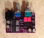
3. Full version, populated, top
4. Full version, populated, bottom
5. Portable version, populated
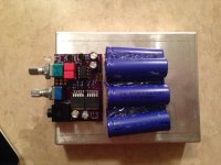
6. Portable with 6x 3.7v (22.2v total, 725mAh) LiPo mockup
7. Portable with 2x 8.4v "9v" (16.8v total, 200mAh) NiMH mockup
I'm thinking for the portable version I'll go with the LiPos, mostly for increased capacity, but the increased voltage will help it run more closely to the full-sized version. As soon as I work out the charging circuit, I'll order PCBs that will have both the battery charging circuits and the inputs.
Thanks for everyone's interest!
🙂
Anyway, I have good news to report! My PCBs came, and I've assembled most of them. I sent out designs for both the full-size version and the portable size. Like I mentioned earlier, I used oshpark.com for them, and I'm very pleased with their service-the PCBs are exactly as I'd designed them, high quality, very quick, and awesome customer service.
Unfortunately I can't actually use either yet since I'm waiting for a more appropriate transformer (will put out 14-CT-14 @ 2A) & some charging ICs from Digikey.
The pics are, in order:
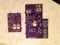
1. Bare PCBs, top layer
2. Bare PCBs, bottom layer
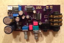
3. Full version, populated, top
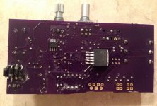
4. Full version, populated, bottom
5. Portable version, populated
6. Portable with 6x 3.7v (22.2v total, 725mAh) LiPo mockup
7. Portable with 2x 8.4v "9v" (16.8v total, 200mAh) NiMH mockup
I'm thinking for the portable version I'll go with the LiPos, mostly for increased capacity, but the increased voltage will help it run more closely to the full-sized version. As soon as I work out the charging circuit, I'll order PCBs that will have both the battery charging circuits and the inputs.
Thanks for everyone's interest!
🙂
Attachments
Its looking good 🙂
Hard to say what has happened to the regs. The vital thing is the input/output differential rating isn't exceeded which I think is 20 volts for these. That's the voltage seen across the reg but you have to include transient conditions in that to such as start up and shut down (where strange things can happen). So its a bit strange what has happened. Hopefully the lower tranny voltage will be a fix and that lower voltage will cause the heat to come right down.
Hard to say what has happened to the regs. The vital thing is the input/output differential rating isn't exceeded which I think is 20 volts for these. That's the voltage seen across the reg but you have to include transient conditions in that to such as start up and shut down (where strange things can happen). So its a bit strange what has happened. Hopefully the lower tranny voltage will be a fix and that lower voltage will cause the heat to come right down.
Thanks for the reply as always, Mooly!
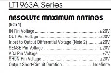
I think I found the problem with at least the 1963s....maximum input voltage is 20V. It specifies -30v on the 3015's datasheet, but I wonder if that's a typo since the 1963 and 3015 are positive and negative "cousins" of each other. Oh well, hopefully it's in the past with the new transformer.
I think I found the problem with at least the 1963s....maximum input voltage is 20V. It specifies -30v on the 3015's datasheet, but I wonder if that's a typo since the 1963 and 3015 are positive and negative "cousins" of each other. Oh well, hopefully it's in the past with the new transformer.
Attachments
Hmmm, wouldn't like to say on that tbh. I wouldn't count on it being an error.
(not sure if you have done this but it can be worth adding "catch diodes" to power supplies which are nothing more than reverse biased diodes across each rail and across each reg. It just clamps any momentary reverse bias condition that can occur as rails initially build (rise unequally) and collapse)
(not sure if you have done this but it can be worth adding "catch diodes" to power supplies which are nothing more than reverse biased diodes across each rail and across each reg. It just clamps any momentary reverse bias condition that can occur as rails initially build (rise unequally) and collapse)
I think I found the problem with at least the 1963s....maximum input voltage is 20V. It specifies -30v on the 3015's datasheet, but I wonder if that's a typo since the 1963 and 3015 are positive and negative "cousins" of each other..
Yep, that's the problem. 🙂 That input voltage difference between the LT1963A and LT3015 is why I said this:
If you want to go for some extra credit DIY work, follow those 317/337s with a LT1963A/LT3015 pair for even lower cascaded ripple and noise. Set your LM317/337 "pre-regulators" for at least a volt more than your output, so +/-16Vdc if you are shooting for +/-15Vdc out of the LDOs, which leaves a volt across the LT LDOs.
The primary purpose of the pre-regulators is to drop the incoming voltage below 20Vdc for that LT`1963A chip. Ripple and noise reduction are just secondary by-products of the pre-regs. I did exactly the same thing with the power supply in this amp:
http://www.diyaudio.com/forums/headphone-systems/229934-version-o2-desktop-amp-oda.html
LM317/LM337 followed by the LT1963A/LT3015 with the pre-regulators set for 18Vdc or so. I was wondering how you were getting that input voltage down enough when you left off the pre-regs.
Sorry about the fried chips! I was just assuming that you had spotted that voltage difference on the data sheet. I've posted so much about the whole problem in that ODA thread I guess I just assume its common knowledge by now. If your lower voltage transformer is still too high you can put diode(s) in series with the power going into the LT chips to drop it 0.7 at a time until you get the input below 20V.
Last edited:
Yep, that's the problem. 🙂 That input voltage difference between the LT1963A and LT3015 is why I said this:
The primary purpose of the pre-regulators is to drop the incoming voltage below 20Vdc for that LT`1963A chip. Ripple and noise reduction are just secondary by-products of the pre-regs. I did exactly the same thing with the power supply in this amp:
http://www.diyaudio.com/forums/headphone-systems/229934-version-o2-desktop-amp-oda.html
LM317/LM337 followed by the LT1963A/LT3015 with the pre-regulators set for 18Vdc or so. I was wondering how you were getting that input voltage down enough when you left off the pre-regs.
Sorry about the fried chips! I was just assuming that you had spotted that voltage difference on the data sheet. I've posted so much about the whole problem in that ODA thread I guess I just assume its common knowledge by now. If your lower voltage transformer is still too high you can put diode(s) in series with the power going into the LT chips to drop it 0.7 at a time until you get the input below 20V.
Thanks for the reply, agdr! I really should read through the ODA thread, I really like my O2, and I can't imagine how the ODA would sound.
I should have read the datasheet more carefully before I employed them, I'm looking at it as a learning experience. 🙂 A while back I did try the 317/337 followed by 1963/3015 combo, and it worked great, but I ultimately decided on just the LT chips since they worked so well on their own. I think once I get the lower voltage transformer everything should work just fine. And if not, like you said, I'm planning on placing a few diodes to drop the voltage to a more apppropriate value. Thanks for suggesting the LT chips to me BTW, before I worked on this project the only voltage regs I was aware of were LM78xx/79xx and LM317/337.
JoeB83 - sorry about the delayed reply, between the holidays and a bunch of stuff going on I'm just now getting back to threads in this forum. 🙂 I really should have mentioned that input voltage difference too, and the role of the pre-regs in reducing it. Kind of an important detail! Please post how your lower voltage transformer worked out. You would only need the diodes in series with that LT1963A reg of course, that 3015 is good for the 30V.
Screwy situation that LT made "complimentary" chips (the data sheets do reference each other as complimentary parts!) that are not entirely complementary, but that is what you get with LT. I've used relatively little of their stuff because it always seems there is at least one big "gotcha" like this on every chip lurking in the datasheet details. One parameter that is off in the night, while the rest of the chips specs look great.
Hey I would agree with Mooly that you've done an excellent engineering job on your amp all in all! Great work. 🙂
JoeB83 - sorry about the delayed reply, between the holidays and a bunch of stuff going on I'm just now getting back to threads in this forum. 🙂 I really should have mentioned that input voltage difference too, and the role of the pre-regs in reducing it. Kind of an important detail! Please post how your lower voltage transformer worked out. You would only need the diodes in series with that LT1963A reg of course, that 3015 is good for the 30V.
Screwy situation that LT made "complimentary" chips (the data sheets do reference each other as complimentary parts!) that are not entirely complementary, but that is what you get with LT. I've used relatively little of their stuff because it always seems there is at least one big "gotcha" like this on every chip lurking in the datasheet details. One parameter that is off in the night, while the rest of the chips specs look great.
Hey I would agree with Mooly that you've done an excellent engineering job on your amp all in all! Great work. 🙂
Hey, no worries. I should have studied the datasheet more carefully. Well, I finally got my transformer and tried to power everything up-as I worried, my first PCB design sucked. Seriously, it was the first PCB I'd ever designed and I forgot to double check for vias hitting neighboring tracks, making sure the tracks themselves are properly laid out and weren't crossing where they shouldn't, and so forth. I did all three. I designed a new one, taking extra time and triple checking my work, and finally, success! It sounds and looks fantastic! I'm so proud to have the first serious project I've taken on by myself (obviously, with lots of help from diyAudio, most notably Mooly and agdr! Thank you so much!) turn out so well and [finally] accomplish everything I had set out to do. Too tired to do much other than listen to it and write this post right now, I'll have some test data later.
I've also posted pics of my next project.....a USB-based DAC. The original is not my own, but I did design the board and modify significant parts of the circuit, mainly with the output stage and power supply. If anyone is interested, it's under the JEDAC thread in Digital Line Level.
Thanks again to all of you who helped, especially Mooly and agdr!!!


- Status
- Not open for further replies.
- Home
- Amplifiers
- Headphone Systems
- My first HPA design...comments please!