I'm reading 640mV across R18. I get 5.2 volts across a 1k0 resistor from ND to the servo. 620 mV across PD and ND with no bias current flowing on the outputs.
Something is wrong.
640mV across R18 gives us 5.3mA through the buffer's output pair (two MJE340).
The same current goes through Vbe multiplier of the output section (if commected correctly). More than enough for comfort biasing...
640mV across R18 gives us 5.3mA through the buffer's output pair (two MJE340).
The same current goes through Vbe multiplier of the output section (if commected correctly). More than enough for comfort biasing...
Are you using your version of PCB from the post#46?
Are you sure PD+ and ND- are not shortened there?
I just can't see if the traces are on the same side or not...
Are you sure PD+ and ND- are not shortened there?
I just can't see if the traces are on the same side or not...
I've got an issue with the output board. I've just tried to test another input board and am having the same issue with it. I've done a few corrections on the board since the one in post #46.
Hey Valery,
Can you peek in on the Slewmaster thread? Since the Krypton-V has your name on it, maybe you can give some suggestions to help get it working.
Thanks, Terry
Can you peek in on the Slewmaster thread? Since the Krypton-V has your name on it, maybe you can give some suggestions to help get it working.
Thanks, Terry
Hey Valery,
Can you peek in on the Slewmaster thread? Since the Krypton-V has your name on it, maybe you can give some suggestions to help get it working.
Thanks, Terry
That's in the Slewmaster build thread I think.
I'm back to getting these things running again. Do I need extra drive current on the input to these? My test signal from my scope drops to zero volts like a short as soon as I install a tube.
I'm back to getting these things running again. Do I need extra drive current on the input to these? My test signal from my scope drops to zero volts like a short as soon as I install a tube.
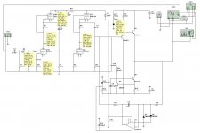
Hi Jeff, no - if it's built according to schematic as shown in >Post #35< - it just works...
What is your scope connected to?
I have my signal generator and scope both hooked to the input. As soon as I install a tube in U1 my input voltage goes to zero.
I have my signal generator and scope both hooked to the input. As soon as I install a tube in U1 my input voltage goes to zero.
Something is wrong... the tube has got high input impedance, so in general it doesn't influence the signal. What are the voltages at the grid, cathode, anode (pins 7,8 ,6)?
My tube connections are opposite yours. 1 = 238V 2 = 238V 3=0. My supply voltage is sagging to 238VDC when I connect a meter.
Just a practical concern who is making these low power tubes these days? After all, tubes are precision mechanics ... expensive to produce with tight specs . Of course high power tubes for FM and TV transmitters have some market where prices doesn't matter much...but even this market dwindles, digital radio satellite tv, broadband internet tv...tubes, notwithstanding their excellent characteristics in terms of amplification, are nostalgia..we have to cope with that.
My tube connections are opposite yours. 1 = 238V 2 = 238V 3=0. My supply voltage is sagging to 238VDC when I connect a meter.
Jeff, see the key measurements here (attached). Grid is almost zero, cathode is +4.29V, anode +137V (may slightly vary)...
Attachments
My components are a little different. C5 in mine is 2.2uF. I'll try to work through it and figure out what is up. The high voltage on my grid and triode don't look good. Thanks.
My components are a little different. C5 in mine is 2.2uF. I'll try to work through it and figure out what is up. The high voltage on my grid and triode don't look good. Thanks.
Yes, it looks like shortened grid-anode... very strange
- Status
- Not open for further replies.
- Home
- Amplifiers
- Solid State
- lGl-2, continuing "hybrid madness" - no GNFB class A