Started preparing for prototyping.
Valery
Helo Valery. In your schematic in post #9, Why do you use capacitor C2 ?
You have a DC Servo loop anyway .....
Maybe I like too much risk ... but why not throw the capacitor totally out, adjust the DC levels on its right and left hand side, and route the DC servo output to the whereabouts of the input tube to maintain control of DC conditions ?
Just curious ... Is it a "better safe than sorry" type of thing ?
Ziggy.
Started preparing for prototyping. I will build the front-end and the buffer at separate PCBs, so that I can experiment with different combinations. This is going to be interesting 🙂
Cheers,
Valery
Valery - When I look at the front end in most recent schematic - I came up with the immediate association that it simply BEGS for an AIKIDO extension. TubeCad John Broskie style. Imply take this (almost) aikido stage and re-strap it to a TRUE Aikido. This way, you shall greatly increase the Power Supply Rejection Ration - the circuit (front-end!) will be dead quiet and almost totally immune to any leftovers of Power Supply noise. This shall maybe mean adding additional tubes, but the ones You suggested using are of the affordable type, I gather ...
Cheers,
Ziggy.
Helo Valery. In your schematic in post #9, Why do you use capacitor C2 ?
You have a DC Servo loop anyway .....
Maybe I like too much risk ... but why not throw the capacitor totally out, adjust the DC levels on its right and left hand side, and route the DC servo output to the whereabouts of the input tube to maintain control of DC conditions ?
Just curious ... Is it a "better safe than sorry" type of thing ?
Ziggy.
Actually, I thought about DC coupling for some time, but then I decided to try decoupled stages first. And then we'll see... step by step 😉
Valery - When I look at the front end in most recent schematic - I came up with the immediate association that it simply BEGS for an AIKIDO extension. TubeCad John Broskie style. Imply take this (almost) aikido stage and re-strap it to a TRUE Aikido. This way, you shall greatly increase the Power Supply Rejection Ration - the circuit (front-end!) will be dead quiet and almost totally immune to any leftovers of Power Supply noise. This shall maybe mean adding additional tubes, but the ones You suggested using are of the affordable type, I gather ...
Cheers,
Ziggy.
Ziggy, I am not really familiar with AIKIDO concept, however I will take a look at it for sure if you think it makes sense. I will prototype this one anyway - PCBs are ready, however - good to have ideas for the future

Cheers,
Valery
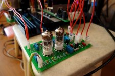
Here comes the tube sound
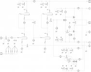
OK, I have slightly simplified my initial schematic and here is the prototype.
I run it in combination with MOSFET output stage (based on Ostrippers Slewmaster), class AB.
No global NFB. Only DC servo and a tiny 2.2pF lead compensation cap (just in case, it actually runs fine without it).
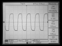
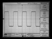
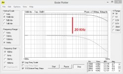
First good things. Very good frequency and phase responses. Wide-band and smooth. Square wave response is excellent. It is decent even at 100 KHz (measured at 20V amplitude). Raise/fall times are around 800 nS (RF filter is in place).
Not so good thing - PSRR. Ziggy - you were right, proper AIKIDO would make it better.
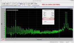
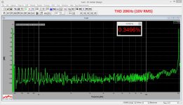
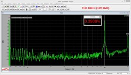
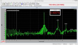
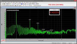
THD. High dominance of 2-nd harmonic (no surprise). 3-rd harmonic is mostly coming from the OPS (remember? no global NFB), although its level is below 0.05%, which is fine. Not bad though. Some "noise" on the spectrums - 50Hz products, result of PSRR not good enough. IMD is also rather high, but I suspect this is the consequence of the high 2-nd harmonic in general.
Now - the funny thing. It works, it plays, and... it sounds! 🙂
I'm auditioning it right now and I could never imagine the amp with no NFB and up to 0.5% of the 2-nd harmonic sounds so good. Comparing to Low TIM hybrid, the bass is slightly less controlled and the sound in overall is somewhat "sweeter".
Stay tuned! 😉
Cheers,
Valery
OK, I have slightly simplified my initial schematic and here is the prototype.
I run it in combination with MOSFET output stage (based on Ostrippers Slewmaster), class AB.
No global NFB. Only DC servo and a tiny 2.2pF lead compensation cap (just in case, it actually runs fine without it).
First good things. Very good frequency and phase responses. Wide-band and smooth. Square wave response is excellent. It is decent even at 100 KHz (measured at 20V amplitude). Raise/fall times are around 800 nS (RF filter is in place).
Not so good thing - PSRR. Ziggy - you were right, proper AIKIDO would make it better.
THD. High dominance of 2-nd harmonic (no surprise). 3-rd harmonic is mostly coming from the OPS (remember? no global NFB), although its level is below 0.05%, which is fine. Not bad though. Some "noise" on the spectrums - 50Hz products, result of PSRR not good enough. IMD is also rather high, but I suspect this is the consequence of the high 2-nd harmonic in general.
Now - the funny thing. It works, it plays, and... it sounds! 🙂
I'm auditioning it right now and I could never imagine the amp with no NFB and up to 0.5% of the 2-nd harmonic sounds so good. Comparing to Low TIM hybrid, the bass is slightly less controlled and the sound in overall is somewhat "sweeter".
Stay tuned! 😉
Cheers,
Valery
Attachments
-
 00 Tube No GNFB sch.jpg368.1 KB · Views: 701
 -
 04 Tube No GNFB 01.JPG295 KB · Views: 347
 -
 03 IMD 14-15K.jpg338.3 KB · Views: 184
 -
 02 THD 20K.jpg321.9 KB · Views: 170
 -
 02 THD 10K.jpg325 KB · Views: 191
 -
 02 THD 04K.jpg323.1 KB · Views: 207
 -
 02 THD 01K.jpg345 KB · Views: 526
 -
 01 SQR 100KHz.JPG297.8 KB · Views: 534
 -
 01 SQR 020KHz.JPG325.1 KB · Views: 547
 -
 01 Bode-01.jpg97.1 KB · Views: 656
Member
Joined 2009
Paid Member
Nice work ! - I am feeling the urge to make a hybrid of my own 🙂
That output stage has much in common with what I call a JLH follower.
I remember a hybrid a friend of mine made. It had a common chathode triode input stage for voltage gain. The output stage was a triple EF open loop. Not the same as your hybrid but what they both have in common is no global nfb, push-pull bipolar output and a tube VAS up front. I do remember that it sounded good, bass was less punchy than a SS amp but still good and the treble was really good like an all-tube amplifier. It fell apart at high power, but it wasn't the goal to have high power, just good sound.
The aikido concept is very good (ultimately I trace back this kind of approach to Loftin White who did early work in cancelling power rail ripple) but you can also achieve good result if you clean up the power rails (more regulation or more CRCLC etc.)
Do you think that you can reduce the IMD with some tweaks to operating points ?
Last edited:
Really like this new direction!
If Matti Otala was right, the best way to reduce TIM distortion is to eliminate GNFB-which you've done.
Now, we need to make the OPS more linear by matching the devices, trying other devices like the BUZ90XP series Mosfets:
http://www.farnell.com/datasheets/49892.pdf
or, better yet, running them in Class A.
Member
Joined 2009
Paid Member
I believe we've moved on since Otala and a well designed amplifier with gnfb will not have any issues with TIM. However, there are other things interesting about no feedback such as the harmonic profile, the output impedance / general interaction with the load, elimination of compensation networks etc. But you have to put more effort into the power supply (gnf improves PSRR).
I almost forgot that I was thinking along these lines before: http://www.diyaudio.com/forums/solid-state/174126-best-topology-no-feedback-classab-buffer.html - this is the kind of direction I have been taking but haven't got around to making anything !
Also see here: http://www.diyaudio.com/forums/soli...50-mk2-circuit-descr-arround-q12a-wanted.html
http://www.ant-audio.co.uk/Theory/Comparision1.gif
Last edited:
Jim, Gareth - thanks for the links.
I have added one more cap multiplier to +220VDC rail - solved the "ripple" issue completely. Dead silent.
I'm going to try an error correction approach, starting with the OPS designed by Sergio and Damir. Looks very good.
Laterals - another interesting area. Lots of things to work on and try 🙂
But you know what? It sounds great even with the existing AB-class OPS with HEX-FETS...
At some genres, like Spyro Gyra's jazz compositions, I like it better than a super-linear Low TIM Hybrid. A colleague of mine considers it as a "true tube" sounding. Still not sure if this is good or bad (my previous nature is "super-linear"), but at least this is what the intention was for this one 😉 And I like this "new" direction
I really like your harmonic profile..
I think 0.5% of THD with something similar to your harmonic profile should be something that we should after if we want "tube sound" from a hybrid.
I have managed to make the same profile but my THD is too low.. I'm afraid it would sound too "sterile". Funny that now i want to distort my amp more 🙂
What do you use to make PCB?
I hope you're not saying Eagle cause it's expensive. The free version allows only small PCB size.
I'm currently learning Design Spark but sadly i don't think there's a library for tubes.
I read that Kicad has tube library..
I really like your harmonic profile..
I think 0.5% of THD with something similar to your harmonic profile should be something that we should after if we want "tube sound" from a hybrid.
I have managed to make the same profile but my THD is too low.. I'm afraid it would sound too "sterile". Funny that now i want to distort my amp more 🙂
What do you use to make PCB?
I hope you're not saying Eagle cause it's expensive. The free version allows only small PCB size.
I'm currently learning Design Spark but sadly i don't think there's a library for tubes.
I read that Kicad has tube library..
Yes, I also realized high 2-nd harmonic doe not scare me any more 😀
It sounds cool. Experimenting with some alternative configurations, including the one with a "light" NFB (~6db loop gain).
I use DipTrace for my layouts:
DipTrace - Schematic and PCB Design Software
They've got a free license among the others.
I've tubes lib for it, it is also very easy to created your own components if required - did it a number of times with great success.
I can give you more details in private mail...
Cheers,
Valery
Beautiful work Valery. I like this very much and would like to build my own inter-stage coupled tube amp some day!

As built
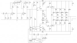
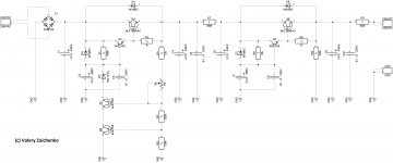
Responding to a number of requests, here is the schematic "as built" at the moment. No global NFB. Rock stable (no surprise 🙂). Voltage gain - tubes only.
My initial intention was to build a class "A" or "AB"+EC OPS for it, however now I'm not sure I need it - it sounds excellent the way it is. Vacuum tube sound, relatively "bright", with cool bass, definitely with its own "signature", very pleasant one.
I use regulated +250v PSU with additional cap multiplier for the front end.
Protection board info is >HERE<
Zobel network is not shown at the output - it's rather standard.
Cheers,
Valery
Attachments
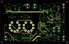
Updated PCB
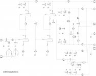
Just a better resolution schematic of the front-end section.
Updated PCB gerbers are available on request.
I will publish high voltage regulator a bit later after minor updates.
Have fun,
Valery
Just a better resolution schematic of the front-end section.
Updated PCB gerbers are available on request.
I will publish high voltage regulator a bit later after minor updates.
Have fun,
Valery
Attachments
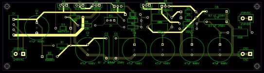
250VDC Regulator
Here it is. High voltage regulator with extensive filtering. Excellent ripple suppression.
Heatsink is not required, however all transistors are placed on one side (just in case).
Cheers,
Valery
Here it is. High voltage regulator with extensive filtering. Excellent ripple suppression.
Heatsink is not required, however all transistors are placed on one side (just in case).
Cheers,
Valery
Attachments
Member
Joined 2009
Paid Member
Wow, two stages of regulation, that's fantastic.
And I guess you intend that a transformer is required between AC supply and the rectifier (for safety).
I would suggest you increase R7 as you have low current draw and lots of voltage to throw away, why not get a bit more RC filtering there with a few kohm ?
Do you need a bleeder resistor to discharge C1 after power-down ?
I don't have the expertise to comment on the pcb but there are some clear guidelines available about layout for high voltages in terms of safety and performance.
Last edited:
Wow, two stages of regulation, that's fantastic.
And I guess you intend that a transformer is required between AC supply and the rectifier - it is a serious safety issue not to isolate yourself from the mains ?
I would suggest you increase R7 as you have low current draw and lots of voltage to throw away, why not get a bit more RC filtering there with a few kohm ?
Hi Gareth, you are right, the transformer is there, it's just "out of the picture".
R7 - a good idea, something like 2.2K will be fine (I just had couple of 680Rs'from the scrapped board).
I had a single regulator PCB first, but some ripple was there, so I used the same PCB for additional cap multiplier. This one here is actually a combination of those two. This way the amp works fine (noise-wise) and sounds fantastic.
C1 practically discharges through the circuit - I have checked that. 47uF is not too much.
With regards to the layout - I'm sure it may be improved, but 300VDC is not 3000VDC, so I did not worry too much about it 😉
Cheers,
Valery
Last edited:
Here it is. High voltage regulator with extensive filtering. Excellent ripple suppression.
Heatsink is not required, however all transistors are placed on one side (just in case).
Cheers,
Valery
How many VA transformer would be required for a 2 channel version of this and what is the maximum input voltage the supply could accept? I think I found a reasonably priced 50VA transformer for this but it has 250/280 volt output taps. This must be getting close to the 300 volt limits of the MJE340s.
One transformer is enough. 250VAC will be fine (I've got 240VAC from my transformer). It doesn't have to be really powerful - 50VA is ok. You can have two separate regulators if you really want to separate power supplies, or just use one regulator as a simpler option. There is enough filtering on the board to ensure good channels separation.
I've also got 6.3VAC output at the same transformer - it's sort of specially designed for tube pre-amps, providing both anode and heating supplies. But heating may be arrange with a separate one, doesn't matter.
250VAC will give you around 350VAC at the input of the regulator. But my regulator is arranged in a way that each MJE350 will see only less than half of it, so don't worry, their SOAs are fine.
Last edited:
- Status
- Not open for further replies.
- Home
- Amplifiers
- Solid State
- lGl-2, continuing "hybrid madness" - no GNFB class A