Yes ! Now we're cooking. This physical distribution happens naturally associated with anode current.I would share the understanding that space charge is defined as net charge per unit volume. There is a net negative space charge inside an operating triode. Here's how I see it
There is a flux of electrons received at the anode. Flux is defined as the number of particles/charges passing through a surface per second. A flux of positive ions would be a current, a flux of negative charges would be a current too, but by convention we define the direction of flow of current to be that of positive charges - and opposite direction to the flow of negative charges.
In physics we say that Flux is conserved meaning that the electrons are neither created or destroyed during their journey from cathode to plate. This is the same as saying that the current that leaves the cathode must all arrive at the anode - current flows in a continuous circuit.
The current flow through the tube is constant across the vacuum, i.e. the flux of electrons is constant across the vacuum. At the anode they are travelling very fast, having been accelerated by the electric field. Near the cathode they are travelling slowly. For the flux to be the same at both electrodes the local density of electrons must be much higher where they are travelling slowly because the same number of electrons per second must leave the cathode as arrives at the anode. This local density of electrons is Space charge. The space charge is highest near the cathode where the electrons travel slowly, and lowest at the anode where they travel quickly.
Yes, except there is an energy barrier to thermionic emission, and this can be modified in the presence of an electric field, ie controlled. The energy barrier can be thought of as an electrical potential jump at the cathode surface, variable by external field.Bigun said:Electrons inside the cathode have a distribution of energies - a thermal phenomena. Those few electrons with enough energy to escape the collective positive charge of the nuclei of the metal atoms at the surface of the cathode will move into the vacuum. The hotter the cathode the more electrons there are with enough energy (this energy can also be supplied by photons - e.g. ultra-violet light). Once the electrons have left the surface of the hot cathode there is an imbalance of charge between the cathode and the space above it. This acts to attract the electrons back to the metal. There is a sea of boiling electrons at the surface of the cathode and a 'steam' or cloud of electrons above it. This is a well established phenomena.
Because there is a distribution of electron energies inside the metal, there are in principle always going to be some that can escape from the surface. Local electric fields modify the potential barrier that affects their escape but there is always some that escape. There are other mechanisms that allow electrons to overcome the surface potential barrier too - tunnelling effects - which would only be an unnecessary complication to this discussion.
Ha - quite possibly !bigun said:fyi - in terms of mass, a Nitrogen atom hitting an electron is not far off equivalent to a high speed golf ball hitting a mosquito...
Effectively yes. Rate controlled might be a better term. And fortunately the clever physics was done long ago ! Check out Harmann/Waganer 1951 Vol2 pages 18 et seq.You are saying that thermionic electrons could be prevented from leaving the surface of the cathode by the local electric field (between the anode, and/or grid and the cathode). (Somewhat analogous to the way water boiling is prevent by an increase in air pressure.)
Could we check this by (some clever physicist) calculating the average velocity of a thermionic electron leaving the cathode and seeing how much force would need to be produced by the local field to stop it in its tracks!
(Easy for me to say - I know!)
Effectively yes. Rate controlled might be a better term. And fortunately the clever physics was done long ago ! Check out Harmann/Waganer 1951 Vol2 pages 18 et seq.
Herrmann/Wagener Vol 2 pages 18 onward discuss field emission together with thermionic emission, which as I said is not significant in tube normal operation. And as I said it is a mathematical convenience to treat it as affecting the cathode work function. In many calculations it is simply ignored.
It has nothing to do with estimating the electron launch velocity.
Member
Joined 2009
Paid Member
Who said that the ion is 'repelled'? On the contrary, it is attracted (while it remains an ion) but is then slowed down by many collisions (probably mostly elastic).
In an elastic collision there is conservation of momentum and of kinetic energy for the two particles. The ion slows down when it transfers momentum to the other particle - an electron.
If you look up the maths (Elastic and Inelastic Collisions) you can calculate how much energy a ion might lose through an elastic collision with a (stationary) electron. Keep it really simple and consider the case of a head-on collision since then the math is in one-dimension (it's not an over-simplification for this purpose).
The energy lost by an ion after a collision with an electron, as a fraction of it's original energy is ((mi/me -1)/(mi/me +1))^2 -1
where mi is the mass of the ion and me the mass of an electron.
Let's pick a nitrogen ion where mi/me = 25,704. After one collision the ion will have lost roughly 0.015% of it's energy.
Let's say it has 1,000 elastic collisions with electrons. The ion energy is reduced to (0.99984)^1000 = 0.85 of it's energy before any collisions. In other words, it still has 85% of it's energy.
How many collisions will an ion have when it encounters the electron cloud above the cathode (apparently, it needs to be tens of thousands) ?
Last edited:
In an elastic collision there is conservation of momentum and of kinetic energy for the two particles. The ion slows down when it transfers momentum to the other particle - an electron.
Let's say it has 1,000 elastic collisions with electrons. The ion energy is reduced to (0.99984)^1000 = 0.85 of it's energy before any collisions. In other words, it still has 85% of it's energy.
How many collisions will an ion have when it encounters the electron cloud above the cathode (apparently, it needs to be tens of thousands) ?
This is not representative of the situtaion. The true picture is a lot more complicated, and far less collisions are needed.
First, there are two sorts of ions: negative ions (gained an electron) and positive ions (lost an electron). Negative ions and the damage to cathodes they cause are significant in vacuum tubes. H/W 1951, Tomer, and many other textbooks point this out.
With negative ions, as well as actuall collisions, the space charge offers group (as in group of electrons) repulsion before collisions occur.
With positive ions, some collisions will be elastic, with the electron and ion immediately parting ways, with the ion carrying on almost unchanged in velocity and direction. Some collisions will be electron capture, turning the ion into a nuetral atom or molecule. Such collisons are not elastic and change the ion/atom/molecule velocity.
Similarly, when electrons collide with atoms, be they atoms that were atoms before they got to the space charge, or atoms created in a previous collision, an electron may be knocked out, or the electron captured, either way converting the atom to an ion, and again there will be a change in velocity.
Last edited:
Member
Joined 2009
Paid Member
Keit -
Negative ions - it should be the case that those created above the virtual cathode will be accelerated by the electric fields to the anode, not the cathode. So only those negative ions generated from recombination with electrons in the inverted field region near the cathode will be accelerated to the cathode - how much energy do think they'll be able to pick up from the field there ? well the energy they can pick up is roughly equal to the thermal energy of the electrons in the cathode since the process of thermionic emission and the electrostatic attraction of electrons back to the cathode are at equilibrium. It's not going to be very much energy as far as I can see ?
As for collisions in which a positive ion captures an electron from the cloud above the cathode and becomes neutral - how much kinetic energy does the ion lose in this process ? does the electron fall into a lower energy state of a stable orbit around the atom and release energy ?
Last edited:
Eureka !
"The limit of the field strength at the cathode surface is determined by the bond between the coating and the core metal, because the coating or parts of it may be torn the core metal by electrostatic forces if the field strength is too high. And exact limit of the field strength cannot be given, as commercial oxide cathodes mostly have a very rough surface which makes an exact calculation of the field strength impossible. If a smooth surface is produced (..), considerably higher field strengths than with normal coatings may be applied. In this manner, a limit of 400kV/cm may be reached. If the cathode is operated in the [carrier limited] range the field strength calculated from the anode or grid voltage will only exist at the cathode surface during the warming-up period. When the cathode reaches the normal temperature, the field strength decreases almost to zero due to the formation of [charge carriers]. The conditions when the heater supply is switched on are therefore particularly important and the application of the oxide cathode may be limited by these conditions.
Hermmann/Waganer 1951 Vol1 1.2 page 9 et seq. I took the liberty of subbing 'charge carrier' for 'space charge' to aid common understanding.
So that's it I reckon. Protecting the cathode from stripping apparently has nothing to do with ion bombardment, dense electron clouds etc - which is why none of that made any sense and couldn't be resolved.
A footnote as to the 2.5x rule, otherwise a loose end. Here's further quote from Hermmann/Waganer 1951 Vol1 1.2 page 9 et seq :
"The density of the emission current is limited, because the oxide coating is heated by the emission current flowing through the coating and this heating may destroy the coating."
Phew ! Hey does this do it for the "Lets settle the b+ on cold tubes issue! ", Merlinb ?
Last edited:
Here's that quote again, corrected for missing word 🙄
"The limit of the field strength at the cathode surface is determined by the bond between the coating and the core metal, because the coating or parts of it may be torn from the core metal by electrostatic forces if the field strength is too high. And exact limit of the field strength cannot be given, as commercial oxide cathodes mostly have a very rough surface which makes an exact calculation of the field strength impossible. If a smooth surface is produced (..), considerably higher field strengths than with normal coatings may be applied. In this manner, a limit of 400kV/cm may be reached. If the cathode is operated in the [carrier limited] range the field strength calculated from the anode or grid voltage will only exist at the cathode surface during the warming-up period. When the cathode reaches the normal temperature, the field strength decreases almost to zero due to the formation of [charge carriers]. The conditions when the heater supply is switched on are therefore particularly important and the application of the oxide cathode may be limited by these conditions."
"The limit of the field strength at the cathode surface is determined by the bond between the coating and the core metal, because the coating or parts of it may be torn from the core metal by electrostatic forces if the field strength is too high. And exact limit of the field strength cannot be given, as commercial oxide cathodes mostly have a very rough surface which makes an exact calculation of the field strength impossible. If a smooth surface is produced (..), considerably higher field strengths than with normal coatings may be applied. In this manner, a limit of 400kV/cm may be reached. If the cathode is operated in the [carrier limited] range the field strength calculated from the anode or grid voltage will only exist at the cathode surface during the warming-up period. When the cathode reaches the normal temperature, the field strength decreases almost to zero due to the formation of [charge carriers]. The conditions when the heater supply is switched on are therefore particularly important and the application of the oxide cathode may be limited by these conditions."
Member
Joined 2009
Paid Member
So that's it I reckon. Protecting the cathode from stripping apparently has nothing to do with ion bombardment, dense electron clouds etc - which is why none of that made any sense and couldn't be resolved.
Yes - as I have been saying all along, I don't see any physics to explain the fear people have of cathode stripping or the potential protection available from dense electron clouds.
However, even expert written books have to be quoted from carefully. If you read further to the paragraph you quoted you will see that it talks about the risk of particles being pulled off the cathode surface in the context of cathodes coated with poorly adhered uneven particles. And it refers in particular to very high field strengths observed in reverse biased rectifier tubes rather than the conditions to be found in most receiving tubes which will have field strengths hundreds of times smaller, where this effect maybe negligible. For transmitting tubes operating at kV on the anode it may well be an issue prompting the use of different cathode materials. However, from what I understand, it is the vastly longer lifetime of the different emitters that favours them for expensive transmitting tubes. For receiving tubes they are usually too power hungry.
So, whilst it may describe a real mechanism it isn't clear that it represents enough of a hazard to warrant delayed B+ turn on for the kinds of tubes and operating voltages that most of us use in our DIY projects.
And I'm still not sure why a 2A3 is sometimes treated as being more vulnerable.
Last edited:
Very nice concise and clear maths as ever, poplilin. You've derived ρ(x), charge carrier density as a function of distance from cathode, and no surprise confirmed Child/Langmuir into the bargain. ρ(x) is essentially space charge density associated with anode potential V, and φ(x) potential at distance x from the cathode.
I think it is correct and very nice. From equation (14) charge carrier (space charge) density depends solely on cathode-anode spacing and cathode-anode potential difference.
Thanks for your kind words; unfortunately my equations did not convince you about the existence of the electron cloud.
A lot of assumptions to simplify a complex problem, so no surprise the results are just an approximation, but not all is lost.
In Maxwell’s equations, ρ is the total free charge density, actually ρ(x, t), then ρ(x) is NOT essentially “space charge density”, it must take account of both electron cloud and electrons into the current density J.
The trick was
J = ρ(x) v(x) … (8)
Electrons with v(x)=0 do not count, and they are into the cloud.
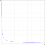
If you are not convinced yet, just see the plot of ρ(x) for about V=300V, d=2mm
Most of the electron cloud is near the cathode
Eureka !
"The limit of the field strength at the cathode surface is determined by the bond between the coating and the core metal, because the coating or parts of it may be torn the core metal by electrostatic forces if the field strength is too high. And exact limit of the field strength cannot be given, as commercial oxide cathodes mostly have a very rough surface which makes an exact calculation of the field strength impossible. If a smooth surface is produced (..), considerably higher field strengths than with normal coatings may be applied. In this manner, a limit of 400kV/cm may be reached. If the cathode is operated in the [carrier limited] range the field strength calculated from the anode or grid voltage will only exist at the cathode surface during the warming-up period. When the cathode reaches the normal temperature, the field strength decreases almost to zero due to the formation of [charge carriers]. The conditions when the heater supply is switched on are therefore particularly important and the application of the oxide cathode may be limited by these conditions.
Hermmann/Waganer 1951 Vol1 1.2 page 9 et seq. I took the liberty of subbing 'charge carrier' for 'space charge' to aid common understanding.
So that's it I reckon. Protecting the cathode from stripping apparently has nothing to do with ion bombardment, dense electron clouds etc - which is why none of that made any sense and couldn't be resolved.
A footnote as to the 2.5x rule, otherwise a loose end. Here's further quote from Hermmann/Waganer 1951 Vol1 1.2 page 9 et seq :
"The density of the emission current is limited, because the oxide coating is heated by the emission current flowing through the coating and this heating may destroy the coating."
Phew ! Hey does this do it for the "Lets settle the b+ on cold tubes issue! ", Merlinb ?
Please, do not scare people!
This is another effect, and for an ECC82
dac ≈ 2mm
dgc ≈ 0.2mm
Then, for a limit of 400KV/cm, you must apply
Vac ≈ 80KV
Vgc ≈ 8KV
Attachments
Last edited:
Another approach
The real world issue is a PITA, because thermionic emission and collisions at low energies into a valve are quantum phenomena, and we should use Fermi-Dirac statistics, then I will try with a rough classical approximation.
Let's consider cathode and anode as infinite parallel plane plates, separated by a distance d, and supposing that between both is placed a charge distribution ρ(x), by Coulomb's law
Then the electric field at point x due to a charge at point x1
By linear superposition, supposing n charges qi at points xi, i=1,...,n; the electric field (k=1, cgs units) will be
Placing the coordinate system on the cathode, we can see from (3) that over electrons near the cathode, the electric field will be
For electrons far away from the cathode
As the cathode constantly produces electrons with some initial velocity towards the cloud, some of them are repulsed and others stay into the cloud, it follows that the electron density is higher near the cathode, i.e. ρ(x) (cloud) is a decreasing function of x.
Let’s suppose now that we apply a constant potential difference V between cathode and anode, ignoring the charge distribution, ρ(x) (cloud), the electric field will be constant, and
Again, by linear superposition, near the cathode
Far away from the cathode
It follows that
Hence, electrons near the cathode are much less affected by the external electric field; electrons far away from the cathode are easily accelerated towards the anode and they abandon the cloud and become part of the beam current
The real world issue is a PITA, because thermionic emission and collisions at low energies into a valve are quantum phenomena, and we should use Fermi-Dirac statistics, then I will try with a rough classical approximation.
Let's consider cathode and anode as infinite parallel plane plates, separated by a distance d, and supposing that between both is placed a charge distribution ρ(x), by Coulomb's law
F = k q1 q2 (x1 - x2) / ∣x1 - x2∣³ … (1)
Then the electric field at point x due to a charge at point x1
E(x) = k q1 (x - x1) / ∣x - x1∣³ … (2)
By linear superposition, supposing n charges qi at points xi, i=1,...,n; the electric field (k=1, cgs units) will be
E(x) = ∑ qi (x - xi) / ∣x - xi∣³ … (3)
Placing the coordinate system on the cathode, we can see from (3) that over electrons near the cathode, the electric field will be
Ex(cloud near) > 0 … (4)
For electrons far away from the cathode
Ex(cloud far) < 0 … (5)
As the cathode constantly produces electrons with some initial velocity towards the cloud, some of them are repulsed and others stay into the cloud, it follows that the electron density is higher near the cathode, i.e. ρ(x) (cloud) is a decreasing function of x.
Let’s suppose now that we apply a constant potential difference V between cathode and anode, ignoring the charge distribution, ρ(x) (cloud), the electric field will be constant, and
Ex(ext) = - V / d < 0 … (6)
Again, by linear superposition, near the cathode
E(near) = ∣Ex(ext) + Ex(cloud near)∣ … (7)
Far away from the cathode
E(far) = ∣ Ex(ext) + Ex(cloud far)∣ … (8)
It follows that
E(near) < E(far) … (9)
Hence, electrons near the cathode are much less affected by the external electric field; electrons far away from the cathode are easily accelerated towards the anode and they abandon the cloud and become part of the beam current
ρ = ρ(cloud) + ρ(beam) … (10)
Last edited:
Member
Joined 2009
Paid Member
Good - some physics instead of ancient scrolls!
I've yet to see any reason to warrant delayed B+?
I've yet to see any reason to warrant delayed B+?
Yes, I agree. One might now at least weigh up the circumstances before deciding to delay B+ or not, knowing something of its reasoning from as good a source as one might get. And there are some interesting aspects, such as whether grid bias without B+ might be more stressful than without for example ?!Yes - as I have been saying all along, I don't see any physics to explain the fear people have of cathode stripping or the potential protection available from dense electron clouds.
However, even expert written books have to be quoted from carefully. If you read further to the paragraph you quoted you will see that it talks about the risk of particles being pulled off the cathode surface in the context of cathodes coated with poorly adhered uneven particles. And it refers in particular to very high field strengths observed in reverse biased rectifier tubes rather than the conditions to be found in most receiving tubes which will have field strengths hundreds of times smaller, where this effect maybe negligible. For transmitting tubes operating at kV on the anode it may well be an issue prompting the use of different cathode materials. However, from what I in some circumstanceunderstand, it is the vastly longer lifetime of the different emitters that favours them for expensive transmitting tubes. For receiving tubes they are usually too power hungry.
So, whilst it may describe a real mechanism it isn't clear that it represents enough of a hazard to warrant delayed B+ turn on for the kinds of tubes and operating voltages that most of us use in our DIY projects.
And I'm still not sure why a 2A3 is sometimes treated as being more vulnerable.
The whole of that Harmmann/Waganer 1950/1951 Vol1/Vol2 text is excellent, IMO. Chapter 12 Vol1 especially well worth a read about other hazards to cathode health. Direct ion bombardment doesn't get a mention. I'm near certain ion bombardment of the cathode is a red herring now, and that's the best way to resolve the numerous contradictions associated with supposed electron cloud protection in my book.
Personally, I've found the deep exploration of cathode emission, carrier transport and potential maps of valves fascinating in this thread. Typically, there's no real reason to really crunch it through, except at times like this when trying to get to grips with what goes on physically and answer questions or resolve contradictions. In this case I find it satisfying to reach a conclusion with some tangible application, and in its own way perhaps restores some of the forgotten wisdom from 1950 I think, so I'm quite pleased for that.
Hey, those scrolls hold the answers, if only we read them well 😉! All one is ever likely to need to know about cathode near field, and carrier generation/density, potential maps is in Harmmann/Waganer 1950/51 I think.Good - some physics instead of ancient scrolls!
@popilin, I do like your approach to maths, popilin BTW !
I've yet to see any reason to warrant delayed B+?
As I said before, serious valve physics must involve quantum descriptions on this issue, and put equations is really difficult, so a condensed phenomenological explanation.
Ion Bombardment
The vacuum in a valve is not perfect, so there are gas molecules randomly floating between the anode and cathode.
If an electron should be accelerated towards the anode from the cathode, there is always a chance that it will collide with a gas molecule and have sufficient energy to remove an electron from that molecule, rendering it positively charged and attracted to a lower potential such as the cathode.
These ions can have a significant energy (momentum) when it strikes the cathode.
Case 1: Vak = 0, Hot Cathode
In metals, at normal temperature, the conduction band is essentially filled of electrons only up to the Fermi energy EF, to extract an electron from the metal is therefore necessary to give a starting energy eφ, but at high temperatures the occupation of electronic states extends above EF.
If the temperature is high enough, some electrons reach energies greater than EF + eφ, and escape from the metal.
If the temperature increases further, the Fermi energy level is widely exceeded and electrons have enough energy to collide with a gas molecule, and have enough energy to remove an electron from that molecule, rendering it positively charged and attracted to a lower potential such as the cathode.
The force acting on the ions, is due to the electric field created by the charge distribution between the cathode and anode, ie. the electron cloud.
F = e E
For simplicity we assume that ions are fermions, then from the Fermi-Dirac distribution, some ions after interacting with the electron cloud, hit the cathode with enough energy (momentum) to be absorbed into its surface.
This phenomenon is called "Cathode Poisoning"
Case 2: Vak = B+, Cathode warms from cold
The cathode starts to warm up.
For simplicity we assume that only one electron is emitted.
This electron is accelerated towards the anode and assuming that collides with at least one gas molecule, and has enough energy to produce an ion.
Now there is no electron cloud, then the force exerted on the ion, is due to the electric field created by the potential difference between cathode and anode.
F = e E = - e grad (φ)
If the ion hits the cathode with enough energy (momentum) to produce sputtering in the cathode.
This phenomenon is called "Cathode Stripping"
Nothing new under the sun.
@popilin, I do like your approach to maths, popilin BTW !
Thank you! Hope that helps.
Last edited:
Member
Joined 2009
Paid Member
The force acting on the ions, is due to the electric field created by the charge distribution between the cathode and anode, ie. the electron cloud.
I tend to think of it a little differently - rather the electric field is created by the potential difference between anode and cathode, and it's non-uniformity is a result of the space charge (aka cloud) but the space charge is not he creator.
Also, whilst it's convenient to think of a Fermi energy when looking at conduction bands, there is a continuous long-tail to the electron energy distribution - even below proper operating temperature for the heater there are some electrons with sufficient energy to escape the surface of the cathode. With B+ applied I wouldn't be surprised if you couldn't measure it with a sufficiently sensitive meter.
Of course there will always be some ion bombardment of the cathode, but I still see insufficient benefit from a delayed B+. In fact a delayed B+ has risks of its own depending on the circuit topology.
Last edited:
.....even below proper operating temperature for the heater there are some electrons with sufficient energy to escape the surface of the cathode. With B+ applied I wouldn't be surprised if you couldn't measure it with a sufficiently sensitive meter.
Indeed you can. And it can be measured even without any B+ applied, though with the cathode only 30% or so below rating, it's then only nanoamps with typical receiving tubes.
The View statistics show that quite a few people are looking at this thread.
For those who came in late, it has been explained by me and others that in general, damage to cathodes does occur if HT is applied immediately upon equipment switch-on without waiting for cathode warm-up. However, in practice the rate at which damage occurs is so slow it makes insignificant difference to tube life. See in particular posts #4, #12, #25.
Ther has been some dicussion about the formation of an interface layer as a diadvantage of delaying HT. This is a non issue. Interface layer formation occurs as a result of adding small amounts of silicon to the cathode tube metal, which improves emission. However the silicon difuses to the surface of the metal, just under the oxide layer, if the cathode is hot, forming a series resistance. If reasonably normal anode current is drawn, interface layer formation is inhibited and any existing layer is gradually destroyed. It is a non-issue in audio with undelayed HT startup, as it is a very slow process in forming and in destruction.
The space charge /electron cloud near the cathode protects oxide coated cathodes from damage from ions. This is a well known fact described in tube books, and the reason why tubes designed to work with kilovolt HT and diodes designed to be operated under staturated conditions do not use oxide coated cathodes.
luckythedog questioned that the space charge /electron cloud near the cathode a) exists during normal operation, and it has been questioned b) even if it did, it couldn't protect the cathode.
There are quite a number of ways to demonstrate the existence of the electron cloud, by theory and by practical measurements - see my posts #26, #52, #76, #86
It is apparent that Luckythedog does not understand J-curve diagrams in tube books, and it may be that others have trouble with them. I therefore include below a short "J-Curves for Dummies":_
J-CURVES FOR DUMMIES
-----------------------
To make it easier to undertand the basics, I'll make some assumptions. The tube is a planar diode, that is a flat plate cathode, emitting on only one side, parallel with a flat plate anode. I'll assume there is no field emission, only thermionic emission. This is not significantly different to reality for typical tubes.
I'll follow the usuall convention that all potentials and voltages are with reference to the cathode.
Figure 1 shows the situation with the heater unenergised, so there is zero emission. With 30V on the anode. There is then a constant electric field strenth between cathode and anode. The red line plots the electric potential and is a straight line.
(THIS POST IS INCOMPLETE -PLEASE IGNORE WHILE I FIGURE OUT HOW TO INCLUDE GRAPHICS - THANKS, KEIT)
Well, have have several diagrams ready, but haven't yet figured out how to include them.
A bit later... Stuff this, I'll do it in a separate post.
Last edited:
J-CURVES FOR DUMMIES
------------------------
This is intended to help those not familiar with J-curve graphs, often seen in tube theory books, understand what goes on with electron clouds, by convention known as "space charge".
Assumptions: Flat single sided cathode facing a parallel flat plate anode. Thermionic emission form the cathode assumed to be the only form of emission.
Fig 1 shows the situation with no emission, but with +30V on the anode:
http://i58.tinypic.com/29mpydy.jpg
The straight red line descibes the electric potential resulting from the anode voltage.
Fig 2 shows the situation with zero anode voltage but with the heater energised. The cathode is emitting electrons, which form a cloud near the cathode. Most don't go far from the cathode because having left the cathode, they must be more negative than the cathode. Thus the electric potential is depressed around the green reference line by the charge on the electrons in that vicinity. Electrons are contiunually emitted from teh cathode. most sooner or later return to it, but as the launch velocity and direction is random, the cloud progressively thins out toward the anode, and some electrons reach the anode and enter it.
http://i61.tinypic.com/sxyp6r.jpg
To get the electric potential with both thermionic emission and anode voltage applied, we can just add the displacement at each distance from the cathode (Superposition theorem). This is shown in Fig 3:-
http://i58.tinypic.com/re6x.jpg
Notice that the anode potential has shifted the curve progresively upward as you move toward the anode, so the depression due to the electron cloud looks a lot less. But the same number of electrons are still there at the same location.
Well, actually, this is not yet quite right. The anode voltage, being positive, pulls the cloud a little bit toward it, and the anode captures a greater number of electrons than it did when it was at zero volts. So fewer electrons return to the cathode. Fig 4 is Fig 3 corrected for this effect:-
http://i61.tinypic.com/2zpqu85.jpg
I've added a line to show the situation for a higher anode voltage. The dashed line now is the red line from Fig 3 above.
It's now easy to imagine that with a still greater +ve anode voltage, the electric potential depression from the space charge will no longer cross the zero voltage line. But still, there is no large change in the density of the electron cloud assumed. The graph never the less now looks just like the diode graphs in textbooks.
Fig 4 shows the situation with the tube in normal space charge limitted operation - the cathode is emitting more than sufficient electrons to satisfy what is lost to the anode.
If someone asks, I'll post more graphs and explain what happens when a grid is added, and/or with retarding (-ve voltages applied) fields.
Common tubes are not planar. They are of concentric construction, with the cathode isn the centre. This alters the radial distribution of the electron cloud somewhat, and further increases the difference in electric potential depression between cathode and grid compared to between anode and grid (or the differnce in electron concentration - different words meaning the same thing), but doesn't alter the big picture. If someone asks, I can make graphs expalining the minor corrections required for concentric construction.
Can someone tell me how to embed pictures rather than links to a pic sharing site? This is quite tedious to do, and tedious to you to click on the links and close when you are done.
Last edited:
Actually no. It turns out that there is scant, if any, mention of direct ion bombardment of the cathode in serious technical literature, at least as known to this thread. Nor of any supposed protection from ion bombardment afforded by electrons, and scrutiny of the assertion that charge carriers near the cathode might have sufficient density to provide protection appears to readily show contradictions. The definitive reference 'The Oxide Cathode' Hermmann/Waganer in 2 volumes 1950/1951 is comprehensive, yet does not describe such phenomema.The space charge /electron cloud near the cathode protects oxide coated cathodes from damage from ions. This is a well known fact described in tube books, and the reason why tubes designed to work with kilovolt HT and diodes designed to be operated under staturated conditions do not use oxide coated cathodes.
luckythedog questioned that the space charge /electron cloud near the cathode a) exists during normal operation, and it has been questioned b) even if it did, it couldn't protect the cathode.
There are quite a number of ways to demonstrate the existence of the electron cloud, by theory and by practical measurements - see my posts #26, #52, #76, #86
It is apparent that Luckythedog does not understand J-curve diagrams in tube books, and it may be that others have trouble with them. I therefore include below a short "J-Curves for Dummies":_
What that reference does reveal is a definitive reason for advising to delay B+ before cathode is warmed-up. That is unambiguously to avoid electrostatic stress to the bond between the coating and the core metal of an oxide cathode, because the coating or parts of it may be torn from the core metal by electrostatic forces if the field strength near the cathode is too high. Such conditions may exist because of grid or anode potentials before thermionic charge carrier generation has started. This makes sense of the term 'cathode stripping', because that is what is happening, the oxide coating is mechanically torn from the core cathode by electrostatic force.
This neatly explains why oxide cathodes tend not to be found in applications with high electrostatic stress, such as high voltage valves and certain diodes.
Of course, in any given application this might or might not be a real hazard to valve lifetime - empirically it generally doesn't seem to be - but at least one might now consider the factors knowing the underlying mechanism for potential failure.
The reference also advises of a hazard to cathode stripping from cathode current overload, due to resistive heating of the cathode oxide coating, and detachment of it from the core metal, and I venture this might well be origin of the 2.5x rule.
Aside, despite Keit's assertions otherwise, I comprehensively understand the physics of charge carrier generation and transport in valves, concepts of space-charge, potential maps including 'J-curves', all involved maths etc etc etc. Too well, perhaps. I wouldn't sweat it, not only does it turn out to be irrelevant to cathode stripping and B+ sequencing, but 'dummies guides' like Keit's can only serve to confuse unless the underlying concepts are properly understood and portrayed, and that is the crux of so much confusion already on this thread.
Last edited:
- Status
- Not open for further replies.
- Home
- Amplifiers
- Tubes / Valves
- Getter heater & B+ sequencing ?