Anybody have real world experience with the highest port velocities that cause minimal noise/compression?
I'm trying to design a 6th order bandpass which I've nicknamed the Disco Destroyer that takes advantage of the powerful tough 18" type speakers which aren't very efficient in vented boxes.
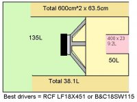
Examples: The no expense spared B&C18SW115 and the cheaper and better value outside the USA: RCF LF18X451.
Overall sensitivity is ~101dB in a 232L total airspace.
Simulations have shown a promising 133dB continuous 1m over the lower 40s to 100Hz at about 110V half space, and 143dB in a corner. This could be one of the loudest relatively compact subwoofers so far! And these are easier to design than a tapped horn. I would need an 18 with 20mm of 1 way Xmax to achieve this in a vented design so I call it a success.
The maximum port velocities are around 30m/s at full whack with the rear chamber low bass ports at 600cm^2 and the front upper bass at 400cm^2. (The lower the tuning, the more port area required) My 12" vented subwoofers seemed to hit ~20-25m/s at tuning and I'd say they were reasonably free of port noise, though the house rattling seems to drown it out!
This seems to reduce slightly in a corner. I will post up my hornresp sims if you are interested.
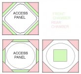
Of course, aero ports would help but are harder to build. They may work on the front access panel though and the rear chamber would have triangular ports in each corner going to the outside.
I'm trying to design a 6th order bandpass which I've nicknamed the Disco Destroyer that takes advantage of the powerful tough 18" type speakers which aren't very efficient in vented boxes.
Examples: The no expense spared B&C18SW115 and the cheaper and better value outside the USA: RCF LF18X451.
Overall sensitivity is ~101dB in a 232L total airspace.
Simulations have shown a promising 133dB continuous 1m over the lower 40s to 100Hz at about 110V half space, and 143dB in a corner. This could be one of the loudest relatively compact subwoofers so far! And these are easier to design than a tapped horn. I would need an 18 with 20mm of 1 way Xmax to achieve this in a vented design so I call it a success.
The maximum port velocities are around 30m/s at full whack with the rear chamber low bass ports at 600cm^2 and the front upper bass at 400cm^2. (The lower the tuning, the more port area required) My 12" vented subwoofers seemed to hit ~20-25m/s at tuning and I'd say they were reasonably free of port noise, though the house rattling seems to drown it out!
This seems to reduce slightly in a corner. I will post up my hornresp sims if you are interested.
Of course, aero ports would help but are harder to build. They may work on the front access panel though and the rear chamber would have triangular ports in each corner going to the outside.
In WinISD Pro I keep 30 m/sec as the upper limit for PA, in Hornresp I use 25 m/sec as the upper limit for semi-PA. However considering the port area I would say you're good to go.
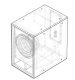
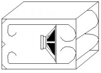
Well here are some pictures of possible port designs I've come up with. Whichever way I can get the driver out would be best!
For anyone wanting to build an equivalent cab to try out, here are some general parameters for the enclosure.
For anyone wanting to build an equivalent cab to try out, here are some general parameters for the enclosure.
Attachments
Last edited:
Tim,Well here are some pictures of possible port designs I've come up with. Whichever way I can get the driver out would be best!
For anyone wanting to build an equivalent cab to try out, here are some general parameters for the enclosure.
Most all the "big boys" are now also including a "top hat" on the inside of the port to reduce port compression and velocity. The "top hat" can take many forms, an example as used in the DSL CS30 (AFAIK, DSL's only BR cabinet) below.
I love the B&C18SW115-4 (should be outside right now doing some additional tests using my pair of Keystone Subs before they are sold), but sorry to say, reading 143dB in a real world corner is not going to happen, unless you use the kind of fanciful SPL readings Meyers (and Martin) seem to come up with.
If you are concerned about port compression, you might look at the Keystone Sub thread. Even with a rather large bass reflex port the BC18SW115 showed significant port compression, while the Keystone using the same driver showed absolutely none, and was 6 dB on average louder (before port compression) than the BR. Your BP design would be louder than a BR, but still exhibit some port compression.
Bonnie, my significant other was highly annoyed to hear the shop walls flapping from 100 feet away when she returned from work yesterday while I was doing amplifier testing using my Keystone Subs yesterday.
As far as Sine 123s response, in response I'll borrow some lines from the Talking Heads:
"When I have nothing to say, my lips are sealed.
Say something once, why say it again?
Psycho Killer,
Qu'est-ce que c'est
fa fa fa fa fa fa fa fa fa far better
Run run run run run run run away"
While I agree with Sine123 that port compression is A Really Big Deal, turbulence noise can also be a big deal with the amount of air an 18SW115 (even more so with an BC21SW152 !!) can fan around.
Art
Attachments
The DSL vent looks like a "butterfly vent / nozzle vent" design (butterfly from the cross section, but if modelled in something like HornResp, the expansion profile looks almost like a nozzle). They are supposed to be better than typical straight vent. I intend to try it out in my next build of a vented alignment. It can be modelled in HornResp
Well here are some pictures of possible port designs I've come up with. Whichever way I can get the driver out would be best!
For anyone wanting to build an equivalent cab to try out, here are some general parameters for the enclosure.
Your port designs may work out to be simpler if you opt to go with a series-tuned 6th order BP alignment instead. A series-tuned system will reduce the length requirement for the rear vent (or allow you to use a larger rear vent of the same length).
are you sure you can put 110vrms on one 18inch? dont think so. burst maybe, but not continuous rms. ihave 2 18nlw9400, each one is rms limited to 60V in my system. i am a bit cautious, right, but given that they all have to get rid of the heat or burn if not, there is no magic. much great kilowatt numbers come from the marketing departments, who have absolutely no idea about physics, thus add no value to any product at all, but how to sell as many units as possible is their more or less superfluous job. what you think some nifty designer fashion built at .2 usd per hour from children would cost if there were no ads or marketing....lol...
what exactly does this port compression do what all guys here are talking about? add some serious thd? would not really give too much s..... about that. you want to rock right? why worry about compression if at the same time bass compressors or enhancers etc. are sold for $$$$, doing exactly that. so what?
just my .02$ 😉
what exactly does this port compression do what all guys here are talking about?
It reduces the subwoofer's low-frequency output at higher input levels. Not the kind of thing you really want to happen with a subwoofer designed for PA use.
Having sent 120 volts 60 Hz sine wave three times, three seconds per time (the time it took to pop the amplifiers 18 amp 120 volt breaker while I figured out I was turning down the HF instead of LF on the crossover) into a BC18SW115-4ohm speaker, then measuring very low distortion using the same driver driven with 77 volt sine waves at multiple frequencies, I am quite certain of both it's average and peak capabilities.are you sure you can put 110vrms on one 18inch? dont think so. burst maybe, but not continuous rms.
60 Hz at 120 volts was loud enough to frighten me, and make a chain saw in another room 30 feet away vibrate off a shelf. Though could not hear the chain saw hit the ground after the 6 foot drop over the distorted 60Hz tone, I am pretty certain it happened on one of the 3 second "oops" tests. 60 Hz happens to be near one of the excursion maxima points in the Keystone Sub, it was not a pleasant experience, but gave me a lot of respect for B&C 🙂.
You can see the actual measured excursion using a lower voltage in the OP here:
http://www.diyaudio.com/forums/subwoofers/185588-keystone-sub-using-18-15-12-inch-speakers.html
Art
Last edited:
The RCF LF18X451 is 1800W AES so 900 Watt sine wave would be the maximum.
100V would be a maximum of 1700 Watt at 76Hz. As I don't tend to play sine waves for extended periods of time it seems to me okay to briefly exceed steady state thermal limits. This is an 8 ohm driver I'm talking about. The 4 ohm version of the B&C I'd limit to 70 or 80 volts, which would be useful for drawing more power out of an amp with less voltage swing but good with 4 ohm loads, which could be a cheaper model of amp.
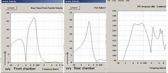
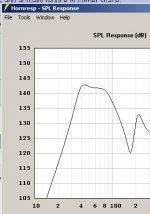
Attached is a graph of SPL in half space and port velocities at 100V RMS.
They peak at just below 30m/s and actually reduce in corner space.
I would expect this to have similar output to sine143's mini tapped horn. I would expect the keystone to be more efficient as it's bigger.
I'm not sure how to model series bandpass or get them to be as flat as this one.
100V would be a maximum of 1700 Watt at 76Hz. As I don't tend to play sine waves for extended periods of time it seems to me okay to briefly exceed steady state thermal limits. This is an 8 ohm driver I'm talking about. The 4 ohm version of the B&C I'd limit to 70 or 80 volts, which would be useful for drawing more power out of an amp with less voltage swing but good with 4 ohm loads, which could be a cheaper model of amp.
Attached is a graph of SPL in half space and port velocities at 100V RMS.
They peak at just below 30m/s and actually reduce in corner space.
I would expect this to have similar output to sine143's mini tapped horn. I would expect the keystone to be more efficient as it's bigger.
I'm not sure how to model series bandpass or get them to be as flat as this one.
Attachments
Last edited:

This is displacement limited SPL in an ideal corner which would be reached at 100V with no power compression. Depending on port compression, the driver is capable of reaching these levels with extra input power.
This is limited to peak displacement of 13.8mm at 45Hz. A bass reflex design would need around 20mm of 1 way Xmax to keep up with this design, along with lighter components to be more efficient in the big box.
Although the keystone measured at 132dB in your link (half space) so I wouldn't expect this to be as loud. I'd imagine under continuous sine waves there would be heating but do you think momentarily it could reach these levels, or at least break the 140 mark, corner loaded? Port velocity at this level in a corner is only around 20m/s. I try and design oversize ports as much as possible. One thing's for sure, it will probably be one of the loudest relatively compact 1 x 18 cabinets available.
My 2 12" were predicted to do 135dB 1m both in the same corner. I have built these and they can violently flicker a lighter flame from several feet out into the room and that's just 3012lf drivers in bass reflex. I can feel it at the "ear popping" level where you can feel it pressurize your ears. The port area on each is 200cm^2. The bandpass design will have 600cm^2 on the lower bass and 400cm^2 on the upper bass, totaling 1000cm^2.
Attachments
Last edited:
18Sound 18nlw9400 are more like the RCF LF18G400 and 401. They would do well in my "DJ's Dream" vented design in a nice big 190L box tuned to 40Hz, and they would surely be sensitive if I scaled up the chambers in this bandpass design, but they aren't the brute beasts those other 18" drivers are. Based on my other designs, 60V would be a sensible limit for those drivers in bass reflex.are you sure you can put 110vrms on one 18inch? dont think so. burst maybe, but not continuous rms. ihave 2 18nlw9400, each one is rms limited to 60V in my system.
Trouble is the B&C is not very efficient in a pure direct radiating vented box. It only needs a tiny 125L enclosure to play flat to 40Hz, but it would consume power like it grows on trees in that application. This I feel is on a level with sine143's mini tapped horn that I think if I can remember he used a faital pro 15HP1030 or something.
The compression will waste power. You're turning up the volume on the amplifiers but you aren't getting much more sound - just more heat in the coils. An ideal loudspeaker would convert a doubling of power into an extra 3dB, but going from 1,000 watts to 2,000 might only yield around 1.5dB if you're on the limits of thermal handling and the airflow the port is capable of passing properly.what exactly does this port compression do what all guys here are talking about? add some serious thd? would not really give too much s..... about that. you want to rock right? why worry about compression if at the same time bass compressors or enhancers etc. are sold for $$$$, doing exactly that. so what?
just my .02$ 😉
Compressing electronically is done before the amplifiers so is not the issue.
Thankfully I don't play huge amounts of continuous sine waves in most of my music, and if I did I'd back off the volume for the duration of the song. Based on what my 2 12" are doing, this cab should be impressive!
Last edited:
Your port designs may work out to be simpler if you opt to go with a series-tuned 6th order BP alignment instead. A series-tuned system will reduce the length requirement for the rear vent (or allow you to use a larger rear vent of the same length).
Generally, series-tuned 6th order systems have both ports tuned to the same frequency. The result is turn-your-head-inside-out bass, but only at one very specific frequency.
I suppose you could tune the inner port low and the outer port high, but surely that just leads to more port compression?
Anyway, here's a paper Google turned up.
http://koti.kapsi.fi/jahonen/Audio/Papers/AES_PortPaper.pdf
Chris
Generally, series-tuned 6th order systems have both ports tuned to the same frequency.
Um, no, I don't think so. Perhaps the ports may be at the same length (to put the out of band "organ-pipe" noise at the same frequency perhaps), but otherwise the tuning is done just like you'd do a normal 6th order BP series alignment.
An example:
Say you've got a norm 6th order BP alignment that requires a 3" vent that's 12" long for the rear chamber and a 3" vent that's 6" long for the front chamber. The equivalent series-tuned system would be one with the same front chamber vent length, but the vent length for the rear chamber should now be around 6" instead of 12" (rear vent length - front vent length). Both the front and rear vents are now the same length, but they are not tuning the chambers to the same frequencies.
The advantage of the series-tuned alignment here is that you can now decide to leave the rear chamber vent at that shorter length, or opt for a larger vent to reduce port compression even further.
I haven't drawn a plan yet. I'm still working out best port designi like you plan timlewis.
did only make the sketh,or have you drawn a plan?
Based on what others have said I wonder if a simplified version of the image below would work better to reduce port turbulence.
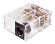
I had a look at one of the acrylic Bose enclosures which is a combination of a 6th order parallel bandpass with a final series ported chamber.
I thought about the complexity of 8th order enclosures and concluded that if you had a design that amplified down to 25Hz, it would roll off around 60Hz, so the outer chamber could be tuned from 80-90 to pick up the trailing top end. I'm not sure how the outer chamber would affect the tuning of the inner chambers though.
Attachments
Last edited:
OK, if the "port compression" is a waste of power / eff. due to heat, it is that thing we call thermal power compression.
OK, if the "port compression" is a waste of power / eff. due to heat, it is that thing we call thermal power compression.
It's not due to heat. It's due to the geometry of the vent (i.e. length, cross-section, flaring at the ends..).
- Status
- Not open for further replies.
- Home
- Loudspeakers
- Subwoofers
- Maximum Port Velocity