Has anyone tried finding the supply voltage limit of the digital side of the 1794?
One wonders if it would allow five volts as the analogue side survives with eight?
Would eliminate a power supply for users of the BLUE mainboard (USB only) if one could power all of the digital devices from the same supply.
I am willing to try if someone thinks it might work.[/QUOTE
I don't understand this. I already have a separate supply for all the digital components. The voltage doesn't matter too much the regulators give the 5v or 3.3v as necessary. Maybe you men something else?
I think he's thinking of feeding the whole deck with a regulated PS, with no local regs, like 8V both sides.
Stop stop stop..... The digital side is 3,3 volt, basta. Everything else will smoke the 1794 chips. Only the analog side can be stretched....
Stop stop stop..... The digital side is 3,3 volt, basta. Everything else will smoke the 1794 chips. Only the analog side can be stretched....
As I said, only if someone (most notably YOU) thought it might work.
I should have known you had probably found the limit.
Thanks for the caution.
 this is really hard limit...
Hi
Hope you can help with a small query. Ive been succesfully using a single board (red)
DDDAC with version 3 DAC boards. Im planning to install the half clock delay mod
so I checked out the signal path. Ive discovered that on my Version 3 DAC the 1K
data path resistor is in fact 100R but the DAC works fine. Is this ok?
Hi
Hope you can help with a small query. Ive been succesfully using a single board (red)
DDDAC with version 3 DAC boards. Im planning to install the half clock delay mod
so I checked out the signal path. Ive discovered that on my Version 3 DAC the 1K
data path resistor is in fact 100R but the DAC works fine. Is this ok?
If using the 1/2 clock delay lc mod the 100r is fine for data
without the mod 1k would have been better
I had the same confusion whether it was 1k or 100r for data when I built the red board
afer some experiments 100r,1k and a few other r values never sounded "right"
thats when I seen the difference in the lc configuration on the blue board
1/2 Clock delay bottom install
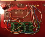
I just built a second 1/2 clock delay circuit board but this time I installed it on the bottom of the red main board which puts it out of sight. I think some of the wires lengths may be a little shorter, but this location is no less time consuming to implement.
I drilled an M3 hole through the adaptor boards and main board with a plastic nut spacer and screw to hold it firmly in place. I used 24ga CAT5e wires. For multiple connections I loop a single wire through the points as much as possible.
Attachments
sorry for being slightly off topic, but to bring all your DDDACs to fullest performance with corresponding food, i.e. music, this seems to be very interesting, as it is about a new ripping procedure regarding high resolution music from no less than Mr. Wicked, the one who made SACD ripping available through a PS3....
so, if interested, have a look here:
Funding? making SACD ripping available through USB!
so, if interested, have a look here:
Funding? making SACD ripping available through USB!
Neat! 🙂I just built a second 1/2 clock delay circuit board but this time I installed it on the bottom of the red main board which puts it out of sight.
If this has been answered a hundred times before - forgive me for being too lazy to look through the pages along with the fact that the DIYAudio search function is not very pinpoint.
AS I am using batteries for the 3.3 v digital side and the 8 volts digital side - I am wondering, after CARLSOR said he thought he perceived that 5 volts on the mainboard was superior to 3.3. Seeing also a similar change in the specs of the isolator chip on WAVE IO when using 5 volts - could I use the same battery to power WAVE IO and the mainboard? Would that harm the isolation - not the chip physically but the amount of isolation one would get?
I know with Dave Davenport's I2S implementation boards for his DAC that the send board had to be powered separately from the DAC to get galvanic isolation.
Trying to eliminate a battery if I can but not at the expense of screwing it up.
The more I think about it (sorry about that) the grounds HAVE to be separate to get isolation?
Am I thinking correctly?
(Yes, this is why I was wondering about the Vdd voltage - two batteries for the DAC board and one for WAVE io - guess it is it will be three for the board iif I remain determined to use 5v for the mainboard.
Anyone else care to speculate on the desirability/need to use 5v for the mainboard instead of 3.3?
Sometimes an image can tell the story better than a complex story. Please take my document from my download section. The 2nd row of the download links, the dddac1794S version. The second page has a block diagram, which very neatly shows how the different voltages are being used. All logic around can handle up to 5 volt. The inputs from the 1794 is also compliant. Using 5 volts just seems to give more headroom... The Vdd for the 1794 chip however is 3.3 volt only. All the rest is HC logic which is compliant over a larger range...
Well the story still reads back complicated, just have a look at the document !
Well the story still reads back complicated, just have a look at the document !
If this has been answered a hundred times before - forgive me for being too lazy to look through the pages along with the fact that the DIYAudio search function is not very pinpoint.
AS I am using batteries for the 3.3 v digital side and the 8 volts digital side - I am wondering, after CARLSOR said he thought he perceived that 5 volts on the mainboard was superior to 3.3. Seeing also a similar change in the specs of the isolator chip on WAVE IO when using 5 volts - could I use the same battery to power WAVE IO and the mainboard? Would that harm the isolation - not the chip physically but the amount of isolation one would get?
I know with Dave Davenport's I2S implementation boards for his DAC that the send board had to be powered separately from the DAC to get galvanic isolation.
Trying to eliminate a battery if I can but not at the expense of screwing it up.
The more I think about it (sorry about that) the grounds HAVE to be separate to get isolation?
Am I thinking correctly?
(Yes, this is why I was wondering about the Vdd voltage - two batteries for the DAC board and one for WAVE io - guess it is it will be three for the board iif I remain determined to use 5v for the mainboard.
Anyone else care to speculate on the desirability/need to use 5v for the mainboard instead of 3.3?
3.3v works fine here for both logic chips/amanero and digital section of the dac chips
I would love to be able to afford $8000 worth of parts to build a tall stack of upgraded DAC boards. Dwjames and I have built fully tweaked single board DACs with an output buffer that provides the drive into a transformer load that a stack of DACs provide. Audio Nirvana for less than $1000. I wish there were more shootouts of various DDDAC builds on the forum.
Next I want to follow Chanh's lead in using the BBB as the digital source device. I shamelessly copy what works for others. I still plan to open a thread explaining all my upgrades and the buffer.
Ross,
From what I heard today, your DAC has already reached Audio Nirvana.
I'm not sure I would change a thing and looking forward to your thread explaining all the upgrades.
Similar to vinyl but with more detail if that makes sense. After today, I think my bank account will be about $1K less by Dec. 1st.
Thank you again for taking the time demonstrating how a DIY DAC can smoke a commercial product costing 10X more.
JS
Sometimes an image can tell the story better than a complex story. Please take my document from my download section. The 2nd row of the download links, the dddac1794S version. The second page has a block diagram, which very neatly shows how the different voltages are being used. All logic around can handle up to 5 volt. The inputs from the 1794 is also compliant. Using 5 volts just seems to give more headroom... The Vdd for the 1794 chip however is 3.3 volt only. All the rest is HC logic which is compliant over a larger range...
Well the story still reads back complicated, just have a look at the document !
Doede, you can be assured I feel I am very familiar with your laudable in its generosity complete documentation. Though that doe snot stop me from making some stupid assumptions and asking some dumb questions.
So do you think I could use the same battery to power the logic chips AND WAVE IO? Sharing the ground of the DAC and the WAVE IO would not affect galvanic isolation?
nige2000, thanks for your comment. I know you have said you hear nothing wrong with 3.3 and I do not doubt your assessment. More than trying to eke out some (imagined?) performance gain I would like to eliminate one battery (well, actually two) and its wiring but not at the expense of goodness.
Thanks,
Last edited:
Hi,
While waiting for the FFs from potatosemi for the Acko S03 reclocker (the first step in my 2nd DDDAC build) I'm considering various output coupling variations / preamp ideas and would very much appreciate feedback on this topic.
My power amp is a Hypex ncore NC400. My idea was to put some kind of passive preamp between the DDDAC and the Hypex. As the Hypex Ncore is sensitive to DC (it seems to simply amplify any DC) some kind of output coupling will be needed at the DDDAC side.
In order to do so I was considering the Cinemag, however, I found out that there are several TVC solution available, which would mean that I could solve the output coupling and the volume control in one step. Moreover, if I understand it right, the balanced outputs of the DDDAC would then fit well to the balanced inputs of the Hypex. What I found was the following:
- The Promitheus TVC (ready made, quality/availability is unclear to me)
- Another DIY solution, "Django" (assembling only, seems a bit outdated)
- A full DIY solution, e.g. with the TVC from sowter:
SOWTER ATTENUATOR TRANSFORMERS TVC VOLUME CONTROL
What I don't know is how well such a TVC would fit to the Hypex NCores and the DDDAC. The input impedance of the Hypex is approx. 100kOhm, which sounds fine, for the output impedance of the DDDAC, I'm unsure. Probably I need 4 decks minimum, right?
Moreover, on the website of the sowter TVC, it reads:
"These transformers should be driven from a source impedance as low as possible but will work well with a source up to 10k ohms. Where necessary a blocking capacitor should be used to ensure no dc is applied to either winding."
This is something I don't get at all: Why would I still need a blocking capacitor?
Another idea of mine was to use a kit from Tortuga Audio | Handcrafted audio gear for music lovers who solve the passive preamp with LDRs, whereas they built in auto calibration in order to overcome the linearity problems of the LDR. The drawback here seems to be that the output coupling issue is unsolved in this case, moreover, LDRs are said to have a very high distortion, in the specs of the LDR kit, 1% THD is mentioned, which seems quite high to me.
Any opinions / recommendations?
Best Regards,
Hermann
Hi,
While waiting for the FFs from potatosemi for the Acko S03 reclocker (the first step in my 2nd DDDAC build) I'm considering various output coupling variations / preamp ideas and would very much appreciate feedback on this topic....
Any opinions / recommendations?
Best Regards,
Hermann
I am using the sowter TVC (9335) directly connected to the balanced output of the DDDAC (single deck !) without any coupling caps going to a pair of mono blocks power amps (300b) at an input impedance of 100k ohm. This combination works very fine for me. I have tested the TVC with an isolation transformer (3575) as well and found out there is no need for that! The 9335 is an excellent TVC and I could even not measure any resonance from 20Hz up to 100KHz !!! ; almost a flat response ;-)
The recommendation of coupling caps in front of the TVC is to make sure there is no DC available at the input of the TVC that could damage it (core magnetizing issue). But the balanced output of the DDDAC is almost DC free so you should not have problem with that configuration (but measure it just to be sure ;-) ) .
I have also tested the LDR solution (even battery driven!!) and found out that they do not come close to a good TVC.
Promitheus TVC are still manufactured (at least until 6 months ago) and have good reputation. Music First Audio (Stevens & Billington) suppose to be one of the best but also one of the most expensive one. I am very happy with my Sowters 🙂 ... Also an alternative could be a special TVC version of the Doede's output transformers . I remember to have seen them some where ... Just ask Doede !
- Home
- Source & Line
- Digital Line Level
- A NOS 192/24 DAC with the PCM1794 (and WaveIO USB input)