Dual subwoofer/media console (L26ROY)
I've been thinking a lot about how to build speakers that will satisfy both my wifes and my preferences. The one large problem (according to my wife) with most of the designs I like is that they are to big. I found a solution that seem to solve these problems: A media console with built in subwoofers.
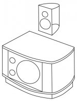
Let's start with some renderings:

Two stained oak sheets (2900x500 mm, 27 mm thick). High gloss white panels from IKEA (BESTÅ TOFTA).

End contains a sealed subwoofer enclosure. On top of console is 4 mm banana connectors for speaker containing midrange/woofer and tweeter.

A total of 6 amplifier channels, placed close to where they are used. Silenced air intake at one end (shown) and outlet at the other. Fans situated at center of space.
The middle space is going to house:
PC
TV-box
Amplifiers
MiniDSP 2x8 + DIGI-FP + VOL-FP (will act as pre-amplifier)
Router
Fans (3 x Noctua 140 mm)
Thunder protected outlets
Not very evident from the renderings is that the center white panel is the only one that opens. It will hide power switches and fuses for all parts.
The reason for the space between wall and subwoofer enclosures is that the right one is at the power outlet on wall and the left one at the TV/broadband outlet.
(Sorry for my crappy English, just ask if I'm not making myself understood.)
/Anton
I've been thinking a lot about how to build speakers that will satisfy both my wifes and my preferences. The one large problem (according to my wife) with most of the designs I like is that they are to big. I found a solution that seem to solve these problems: A media console with built in subwoofers.
Let's start with some renderings:
Two stained oak sheets (2900x500 mm, 27 mm thick). High gloss white panels from IKEA (BESTÅ TOFTA).
End contains a sealed subwoofer enclosure. On top of console is 4 mm banana connectors for speaker containing midrange/woofer and tweeter.
A total of 6 amplifier channels, placed close to where they are used. Silenced air intake at one end (shown) and outlet at the other. Fans situated at center of space.
The middle space is going to house:
PC
TV-box
Amplifiers
MiniDSP 2x8 + DIGI-FP + VOL-FP (will act as pre-amplifier)
Router
Fans (3 x Noctua 140 mm)
Thunder protected outlets
Not very evident from the renderings is that the center white panel is the only one that opens. It will hide power switches and fuses for all parts.
The reason for the space between wall and subwoofer enclosures is that the right one is at the power outlet on wall and the left one at the TV/broadband outlet.
(Sorry for my crappy English, just ask if I'm not making myself understood.)
/Anton
Last edited:
The build actually started a few months ago, but I have 2 kids (3 months, 3 years old) so the pace is quite slow. Here are a few pics from the process so far:
This is one of the cut and sanded oak sheets:

It was stained by pouring Herdins Lackbets (Herdins Lackbets) on and evening it out with this:
It looked like this after four surfaces:

After covering the surface with stain it was quickly removed using a dry microfiber cloth, like this one:
I wanted a surface with a lot of contrast and visible grain. This is the result:

Exactly what I wanted. (The first three surfaces don't look nearly as good, I let the stain sink in too deep which made it too dark and even.)
Testing the layout:

/Anton
This is one of the cut and sanded oak sheets:
It was stained by pouring Herdins Lackbets (Herdins Lackbets) on and evening it out with this:
An externally hosted image should be here but it was not working when we last tested it.
It looked like this after four surfaces:
After covering the surface with stain it was quickly removed using a dry microfiber cloth, like this one:
An externally hosted image should be here but it was not working when we last tested it.
I wanted a surface with a lot of contrast and visible grain. This is the result:
Exactly what I wanted. (The first three surfaces don't look nearly as good, I let the stain sink in too deep which made it too dark and even.)
Testing the layout:
/Anton
Thanks!looks nice ,but why the connections on top?
It felt like the visually cleanest way to get the cable to a speaker standing on the console. Here is a rendering I did (before deciding to move the legs in from the ends) of the end result I'm going for:

The cable will be short (~50 cm) and sleeved. I've bought Supra Classic 4.0 mm² and sleeves (12 mm and 6 mm diameter, link), as well as Nakamichi speaker plugs (link) and connectors (link). Hopefully they will make a nice bi-amp cable together 🙂

/Anton
A few more pics from the process so far
And some questions...
The speaker cabinets were joined using glue and screws:

The only missing part in this picture is a last fir rib that stiffens the bottom panel.
I placed the MDF shell on the top oak sheet (with its top face down) and measured that the cabinet was in the correct positions. Then I outlined the MDF on the oak, removed the MDF shell and added glue:

Then I fastened the MDF shell (after measuring again):

Both MDF shells joined to the top oak sheet:

Before joining the bottom oak sheet (the one with feet) to the MDF shells I need to figure out how the speakers should be stuffed. I had some acoustic panels (fiberglass) over from another project which I found were very easy to cut into shape:

So I filled the two compartments in the back and placed one piece (5 cm thick) on each side wall:

The inner volume is 50 l (after subtraction of driver volume) and sims like this at 140 W (Xmax with HP at 15 Hz) in WINISD:

Qa = 30 (reasonable?), Vc temp rise = 50 K (reasonable?). A little room gain + a little lift using miniDSP should give me decent output (>100 dB) down to 20 Hz.
Question 1: Is this a decent amount of stuffing? I can add the polyester kind (see pic below) after I've joined everything and cut the hole in the baffle, but removing stuffing will be a p.i.t.a.

Another thing that has been on my mind is how vibrations will spread from the speaker to the electronics. The cabinet is built very stiff (IMHO), but there is not a lot of damping of vibrations. The plan is to add a CLD (constrained layer damping) solution to the front. A 3 mm thick foam used for floor damping is adhered to the MDF shell and the high gloss front is adhered to the foam.
Question 2: Will I need more damping? Should I use something like this (bitumen) on some surfaces:

/Anton
And some questions...
The speaker cabinets were joined using glue and screws:
The only missing part in this picture is a last fir rib that stiffens the bottom panel.
I placed the MDF shell on the top oak sheet (with its top face down) and measured that the cabinet was in the correct positions. Then I outlined the MDF on the oak, removed the MDF shell and added glue:
Then I fastened the MDF shell (after measuring again):
Both MDF shells joined to the top oak sheet:
Before joining the bottom oak sheet (the one with feet) to the MDF shells I need to figure out how the speakers should be stuffed. I had some acoustic panels (fiberglass) over from another project which I found were very easy to cut into shape:
So I filled the two compartments in the back and placed one piece (5 cm thick) on each side wall:
The inner volume is 50 l (after subtraction of driver volume) and sims like this at 140 W (Xmax with HP at 15 Hz) in WINISD:
Qa = 30 (reasonable?), Vc temp rise = 50 K (reasonable?). A little room gain + a little lift using miniDSP should give me decent output (>100 dB) down to 20 Hz.
Question 1: Is this a decent amount of stuffing? I can add the polyester kind (see pic below) after I've joined everything and cut the hole in the baffle, but removing stuffing will be a p.i.t.a.
Another thing that has been on my mind is how vibrations will spread from the speaker to the electronics. The cabinet is built very stiff (IMHO), but there is not a lot of damping of vibrations. The plan is to add a CLD (constrained layer damping) solution to the front. A 3 mm thick foam used for floor damping is adhered to the MDF shell and the high gloss front is adhered to the foam.
Question 2: Will I need more damping? Should I use something like this (bitumen) on some surfaces:
/Anton
I admire the design esthetic. Yet [if you like dB as much as I do] I agree that vibration damping for the 'lectronix is advisable and i think a more compliant layer would probably help. There are commercially available vibration damping feet that you might employ on a rigid tray. Also, within the sub cabinets, I suggest polyester material on any internal surface from which internal reflections might reach the rear of the cones.
I have a similar project in mind - based on the exact same 'his/hers' priorities of your build! My solution will be to make the subs nest unobtrusively into the sides of the center console but separated by air. Mine won't look as 'minimal' as yours. [With my drivers I will want more volume than 50l, and I need more internal space for equipment.]
Good work! 🙂
Nice observation! 🙂I like the enclosure color scheme. It reminds me of the dessert "ice cream sandwich" 🙂
Thanks! I try, but writing replies takes some time. Sometimes I'm not sure if the sentences are decipherable...Crappy English?
You have better English than some English people I know... lol
Thanks!I admire the design esthetic. Yet [if you like dB as much as I do] I agree that vibration damping for the 'lectronix is advisable and i think a more compliant layer would probably help. There are commercially available vibration damping feet that you might employ on a rigid tray. Also, within the sub cabinets, I suggest polyester material on any internal surface from which internal reflections might reach the rear of the cones.
I have a similar project in mind - based on the exact same 'his/hers' priorities of your build! My solution will be to make the subs nest unobtrusively into the sides of the center console but separated by air. Mine won't look as 'minimal' as yours. [With my drivers I will want more volume than 50l, and I need more internal space for equipment.]
Good work! 🙂
You recommend that I fill the remaining volume with polyester damping before inserting the driver?
That's awesome, do you have any sketches?
Vibration damping of the electronics will be done for two reasons:
1. Protecting them from speaker induced vibrations.
2. Preventing them to spread vibrations into the structure (this is a problem with my current setup).
My plan is to use a acoustic foam (Auralex 2" Studiofoam Wedges) both for absorption and vibration damping.
An externally hosted image should be here but it was not working when we last tested it.
/Anton
You recommend that I fill the remaining volume with polyester damping before inserting the driver?
/Anton
Not necessarily 'fill'... but cover with sufficient material to avoid reflections onto the rear of the driver cone. For example, with my midrange drivers I can hear benefits to the sound by placing thin damping material on the driver spider opposite the rear of the cones. Preventing reflections is perhaps less critical for stiffer bass driver cones, but DIYers usually are interested in every easy improvement! 😀
That's awesome, do you have any sketches?
/Anton
Very preliminary ideas. For the midrange/tweeter enclosures I'm considering elliptical laminated baltic birch construction, with granite decoration/stiffening on the exterior of flat top and bottom surfaces. [I've been working with stone for other projects lately.] ...slightly domed baffle?
I haven't addressed the 'wife's issues' with the larger woofers and console. ...I'm imagining something softened by curves in front with coordinating stone tops [though weight could become prohibitive]. Perhaps curved grilles and end panels with other panels flat. MDF and Baltic birch structure with nice veneer - not a quick build...
Attachments
Honestly, do not worry - you even have the correct grammar so you are much better than many people over here!!Thanks! I try, but writing replies takes some time. Sometimes I'm not sure if the sentences are decipherable...
Carry on as you were! 🙂
I do wish I could learn languages, but that is another thread entirely... lol
That looks great!Not necessarily 'fill'... but cover with sufficient material to avoid reflections onto the rear of the driver cone. For example, with my midrange drivers I can hear benefits to the sound by placing thin damping material on the driver spider opposite the rear of the cones. Preventing reflections is perhaps less critical for stiffer bass driver cones, but DIYers usually are interested in every easy improvement! 😀
Very preliminary ideas. For the midrange/tweeter enclosures I'm considering elliptical laminated baltic birch construction, with granite decoration/stiffening on the exterior of flat top and bottom surfaces. [I've been working with stone for other projects lately.] ...slightly domed baffle?
I haven't addressed the 'wife's issues' with the larger woofers and console. ...I'm imagining something softened by curves in front with coordinating stone tops [though weight could become prohibitive]. Perhaps curved grilles and end panels with other panels flat. MDF and Baltic birch structure with nice veneer - not a quick build...
Alright, I have the polyester stuffing at hand, so first try will be with it added on remaining surfaces.
Great 🙂Honestly, do not worry - you even have the correct grammar so you are much better than many people over here!!
Carry on as you were! 🙂
I do wish I could learn languages, but that is another thread entirely... lol
I made the remaining inner damping yesterday, as well as a test of painting the middle white panel. It's a transparent acrylic sheet:
This is how the back side (the one with paint) looks:

A little uneven and with a matte finish.
And this how the front side looks:

More even and very glossy. Bigger difference IRL, looks good IMO. Later I will make a wooden frame and heat/bend the acrylic around the edge to get a look similar to the IKEA TOFTA fronts I already have.
/Anton
Finally managed to check out the pics in this thread at home - work blocks everything... 🙄
Looks great! Love the grain, I wish I had your DIY skills!
Is the boss happy with it? 😉 lol
Looks great! Love the grain, I wish I had your DIY skills!
Is the boss happy with it? 😉 lol
Thanks! My woodworking skills are not very evolved and I don't have the best tools. But the design accounts for this, no advanced curved surfaces and so on. 🙂Finally managed to check out the pics in this thread at home - work blocks everything... 🙄
Looks great! Love the grain, I wish I had your DIY skills!
Is the boss happy with it? 😉 lol
The boss seems happy, haven't tried it in place yet, but she likes the renderings.
This weekends progress:
Connectors added for the subwoofers:

Sealed with silicone.

From the inside. Missing nut, washer and soldered connector (see below).

Supra Classic 2.5 soldered to connector. I would call this "lödöra", directly translated that is "soldering-ear", couldn't find a translation...
I've also done a lot of holes... Inlet holes (for ventilation of electronics):

14 mm holes. Done, seen from inside:

Seen from outside:

With added glue.

With speaker cloth attached to the glue. This will act as a dust filter. I originally had a much more advanced design in mind where I could remove the filter to clean it, but decided that i can just use the vacuum cleaner with this permanent solution. This is how it looks from inside:

The outlet holes are angled to direct the hot airflow out from below the console:

Seen from the inside, the front is up in the photo.
/Anton
Simulation of airflow
After drilling all those holes I started worrying that maybe they will restrict airflow too much. So I made a FE model (in COMSOL Multiphysics).
Geometry

I only included the inner space with dividing wall (with fans) and the space below the console.

The blue side is open (open boundary) and the rest are walls (no slip).
Fans

The three fans (Noctua NF-P14s 900rpm) are modeled as having a linear static pressure curve using the only two known parameters for the fans:
Static pressure at 0 flow: 0.77 mmH2O = 7.55 Pa
Unrestricted airflow: 83.7 m^3/h
Dust filter

The dust filter will add a flow resistance, therefore they are modeled (using screen).
Resulting pressure distribution

Outside pressure is set to 0.
Resulting air velocity

Resulting flow
The flow is 10.5 m^3/h. If we assume a heat production of 100 W (corresponding to idle) we get an air temperature of 66 C at the outlet! That's no good...
Questions
Is a linear static pressure curve realistic for my fans?
More holes? Other fans? Put fans in series?
/Anton
After drilling all those holes I started worrying that maybe they will restrict airflow too much. So I made a FE model (in COMSOL Multiphysics).
Geometry
I only included the inner space with dividing wall (with fans) and the space below the console.
The blue side is open (open boundary) and the rest are walls (no slip).
Fans
The three fans (Noctua NF-P14s 900rpm) are modeled as having a linear static pressure curve using the only two known parameters for the fans:
Static pressure at 0 flow: 0.77 mmH2O = 7.55 Pa
Unrestricted airflow: 83.7 m^3/h
Dust filter
The dust filter will add a flow resistance, therefore they are modeled (using screen).
Resulting pressure distribution
Outside pressure is set to 0.
Resulting air velocity
Resulting flow
The flow is 10.5 m^3/h. If we assume a heat production of 100 W (corresponding to idle) we get an air temperature of 66 C at the outlet! That's no good...
Questions
Is a linear static pressure curve realistic for my fans?
More holes? Other fans? Put fans in series?
/Anton
Hi,
FWIW I don't like the look of the structural fibreglass
you are using. It may be too dense, but might be OK,
but you must remove the facing sheeting from it,
except when against the cabinet walls. Heat flow
and sound dampening are very different things.
rgds, sreten.
FWIW I don't like the look of the structural fibreglass
you are using. It may be too dense, but might be OK,
but you must remove the facing sheeting from it,
except when against the cabinet walls. Heat flow
and sound dampening are very different things.
rgds, sreten.
Hi sreten!Hi,
FWIW I don't like the look of the structural fibreglass
you are using. It may be too dense, but might be OK,
but you must remove the facing sheeting from it,
except when against the cabinet walls. Heat flow
and sound dampening are very different things.
rgds, sreten.
The stone wool I'm using is developed specifically for acoustic absorption. Here is a datasheet. It has a density of 40 kg/m^3 and this is the absorptioncoefficient for three thicknesses:
An externally hosted image should be here but it was not working when we last tested it.
I'll take another look at the facing sheeting to see if it looks perforated enough.
/Anton
- Status
- Not open for further replies.
- Home
- Loudspeakers
- Subwoofers
- Dual subwoofer/media console