2SK208 CCS
So far the 2SK208 looks promising. It comes in a "y" version with an Idss of 1.2-3.0ma and an "o" version with an Idss range of 0.6-1.4ma. The "y" (idss=2.7ma) version had a small negative tempco and the "o" (idss=0.9ma) version has an even smaller positive tempco that went from 0.405ma to only 0.408ma when heated way beyond 40C. Theoretically there is an in between Idss value that will have a Zero tempco, but this is plenty good enough for DAC stacks.
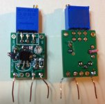
The 2SK208o I tested only had a Vs of 0.27v at 0.4ma so I made a cascoded version. I cannot capture any overshoot spike on my scope from a 0.1V rms square wave fed to it and the current is flat line. Too good to be true. I made a pair of these to burnin for a few days and then give them a listen. Maybe I'm getting closer to the 2 transistor CCS that K&K claims is best.
The next mini-board version should have SMD pads paralleling the TO-92 pads. A pcb with a SMD JFET and resistor will be no larger than the Bourns pot and should fit anywhere. Anyone want to design this for a GB?
So far the 2SK208 looks promising. It comes in a "y" version with an Idss of 1.2-3.0ma and an "o" version with an Idss range of 0.6-1.4ma. The "y" (idss=2.7ma) version had a small negative tempco and the "o" (idss=0.9ma) version has an even smaller positive tempco that went from 0.405ma to only 0.408ma when heated way beyond 40C. Theoretically there is an in between Idss value that will have a Zero tempco, but this is plenty good enough for DAC stacks.
The 2SK208o I tested only had a Vs of 0.27v at 0.4ma so I made a cascoded version. I cannot capture any overshoot spike on my scope from a 0.1V rms square wave fed to it and the current is flat line. Too good to be true. I made a pair of these to burnin for a few days and then give them a listen. Maybe I'm getting closer to the 2 transistor CCS that K&K claims is best.
The next mini-board version should have SMD pads paralleling the TO-92 pads. A pcb with a SMD JFET and resistor will be no larger than the Bourns pot and should fit anywhere. Anyone want to design this for a GB?
Attachments
Looks promising Ross 🙂
Why 3 wires from your board though? Does this setup need a negative rail or 8v supply?
Why 3 wires from your board though? Does this setup need a negative rail or 8v supply?
Also, what's the other component? I can see the surface mount 2SK208o, but what's it paired up with?
Thanks,
James
Thanks,
James
dwjames,
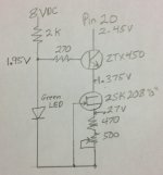
Yes, 8V goes through the 2K resistor to a green LED which provides the gate voltage reference through a 270 ohm resistor to the ZTX450 constant voltage cascode transistor. The 2SK208 source resistance is a 470 SMD plus a 500 pot.
Yes, 8V goes through the 2K resistor to a green LED which provides the gate voltage reference through a 270 ohm resistor to the ZTX450 constant voltage cascode transistor. The 2SK208 source resistance is a 470 SMD plus a 500 pot.
dwjames,
Yes, 8V goes through the 2K resistor to a green LED which provides the gate voltage reference through a 270 ohm resistor to the ZTX450 constant voltage cascode transistor. The 2SK208 source resistance is a 470 SMD plus a 500 pot.
that looks interesting
can you sketch it out please id like to try it
that looks interesting
can you sketch it out please id like to try it
I think it's in post #2622. I thought, though, that carlsor didn't like it relative to the single JFET
I suggest using a lower capacitance BJT than the ZTX450, such as the KSC1845. It will greatly improve the high frequency behavior of the CCS.
Radu.
Last edited:
oh ok
i thought it was more similar to the methods on page 5 of http://waltjung.org/PDFs/Sources_101_P1.pdf
i thought it was more similar to the methods on page 5 of http://waltjung.org/PDFs/Sources_101_P1.pdf
Carlsor,
Congratulations finding something that measures well - a good start.
Can't wait to hear what you hear.
Just to be sure all are understanding what you are doing would you draw a schematic for those of us lacking in conceptual knowledge?
Thanks and take care,
PS where did you find the "o" version? Aha - I see they are at DIGIKEY. Went to MOUSER first ...
Last edited:
cool, thanks.dwjames,
Yes, 8V goes through the 2K resistor to a green LED which provides the gate voltage reference through a 270 ohm resistor to the ZTX450 constant voltage cascode transistor. The 2SK208 source resistance is a 470 SMD plus a 500 pot.
Did you consider a Voltage ref diode instead of the Green LED?
Walt Jung recommended something like this as a green LED replacement in his article
LM336Z25X Fairchild Semiconductor | LM336Z25XCT-ND | DigiKey
I assume you'd either ignore or short the ADJ pin and just treat it as a regular 2 pin diode
these are good
I'm using them in my Shunty regzz as 5V ref , really low noise and low current needed for proper function
whatever - I believe in this role , 2V5 is way too much for cascode reference ;
in fact , almost any cascode is on verge of CCS voltage starving , considering voltage level at pin 20
I'm using them in my Shunty regzz as 5V ref , really low noise and low current needed for proper function
whatever - I believe in this role , 2V5 is way too much for cascode reference ;
in fact , almost any cascode is on verge of CCS voltage starving , considering voltage level at pin 20
cool, thanks.
Did you consider a Voltage ref diode instead of the Green LED?
Walt Jung recommended something like this as a green LED replacement in his article
LM336Z25X Fairchild Semiconductor | LM336Z25XCT-ND | DigiKey
I assume you'd either ignore or short the ADJ pin and just treat it as a regular 2 pin diode
I've asked the same question from carlsor in August, but he never answered...
There is the question of noise vs. rejection, in terms of a tradeoff. LED has less noise, but loses a lot of the rejection that the precision voltage reference offers.
(I also posted on this aspect back in September, I believe)
these are good
I'm using them in my Shunty regzz as 5V ref , really low noise and low current needed for proper function
whatever - I believe in this role , 2V5 is way too much for cascode reference ;
in fact , almost any cascode is on verge of CCS voltage starving , considering voltage level at pin 20
I've used the LT1034/1.2 in the CCS I posted back in August. The less voltage reference voltage, the more headroom and the better performance... The circuit I tried was stable all the way down to about 2V working my way down from 8V, which is also a function of this low voltage from the reference.
I personally think (and I think I've mentioned already, at least to members here in PMs or emails) that any cascode would be too starved of voltage to function properly.
Radu.
Cascoded 2SK208O CCS Diagram
Below is a diagram of the cascoded 2SK208"O" CCS circuit along with measured voltages. This circuit splits the voltage across each transistor to slightly above 1V each. A 2.5V Voltage ref diode would leave too little voltage across the ZTX450 to operate in its linear range.
Below is a diagram of the cascoded 2SK208"O" CCS circuit along with measured voltages. This circuit splits the voltage across each transistor to slightly above 1V each. A 2.5V Voltage ref diode would leave too little voltage across the ZTX450 to operate in its linear range.
Attachments
I am in the same situation with the Tent.
Anyone is aware about a valid alternative?
Regards,
Enrico
dear all,
Sorry for the long delay, my manufacturing has delayed and I have been too thin on communication. I retrieved shunts from a dealer and will ship outstanding shunt orders today.
all the best,
-
Guido
Thanks, Carlsor.
Everyone, as I, assumed you were using two FETs for your CCS.
I know many of us are hoping you have found the best compromise.
Now to hear your appraisal of your handiwork.
THANKS, again!
Everyone, as I, assumed you were using two FETs for your CCS.
I know many of us are hoping you have found the best compromise.
Now to hear your appraisal of your handiwork.
THANKS, again!
Below is a diagram of the cascoded 2SK208"O" CCS circuit along with measured voltages. This circuit splits the voltage across each transistor to slightly above 1V each. A 2.5V Voltage ref diode would leave too little voltage across the ZTX450 to operate in its linear range.
Looks to me like a reasonable solution for a very difficult application.
That said, the exact impedance of the composite source of the JFET + NPN will be subject to the particular JFET, and just where it is operating. From the device DS, it appears that it will be in (or close to) the ohmic region. Thus, performance will vary part-part of the 2SK208.
I could suggest something that might be helpful, for just a bit more experimental work. In place of the GRN LED, a series connected RED LED + one diode will put around 2.2 - 2.3V on the NPN base, still a couple hundred mV above saturation. Most NPNs can work down to 0V Cb (i.e., as a diode, with C-B strapped), so 2.3V at the NPN base should be OK with 2.4V at the collector. Note that you can, should you wish, fine-tune the base voltage by virtue of the current in the LED and diode.
Hope this is helpful!
Walt Jung
Looks to me like a reasonable solution for a very difficult application.
That said, the exact impedance of the composite source of the JFET + NPN will be subject to the particular JFET, and just where it is operating. From the device DS, it appears that it will be in (or close to) the ohmic region. Thus, performance will vary part-part of the 2SK208.
Firstly: thank you for coming into this discussion!
Your thought above suggests that the benefit of using the JFET in that position is diminutive, possibly none with some parts given the spread. With that in mind, would a resistor do and provide most of the benefits?
Radu.
Last edited:
Firstly: thank you for coming into this discussion!
Your thought above suggests that the benefit of using the JFET in that position is diminutive, possibly none with some parts given the spread. With that in mind, would a resistor do and provide most of the benefits?
Radu.
I should have qualified my comments further. Basically, I was saying that the JFET in the ohmic region, due to low Vds, will vary part-part. What I didn't say is that even so, this should be better than the original resistor, which allows noise on the DAC's internal Vref to get into the current.
The JFET could be replaced with a fixed R, but this would then make the circuit sensitive the variations in the LED voltage and +8V supply. The use of the JFET is good in the sense that it decouples the entire circuit from those variations.
Yes, it may be a tweaky thing, but it should be light-y(ears) ahead of the simple R used originally.
And thanks for the welcome..
For those looking for a non-SMD version of this, a JFET from the 2N4338 series, or J201 may work - would you agree?
For the BJT, I suggest going for a low noise / low capacitance type, such as KSC1845 and others (or your recommended - but less available and more expensive - 2SC2362), for better HF performance.
For the BJT, I suggest going for a low noise / low capacitance type, such as KSC1845 and others (or your recommended - but less available and more expensive - 2SC2362), for better HF performance.
Last edited:
Carlsor summons an audio god into the discussion!
Well done!
Is selection necessary for the circuit? If so, what are the recommended parameters?
Well done!
Is selection necessary for the circuit? If so, what are the recommended parameters?
Last edited:
- Home
- Source & Line
- Digital Line Level
- A NOS 192/24 DAC with the PCM1794 (and WaveIO USB input)