I was wondering if anyone has any input on this:
I am designing a circuit where I need to buffer some audio, outputting both an in phase as well as an inverted signal. The stage after this adds a lot of gain, so I need to get the noise floor as low as possible.
I used an opa2134 because it's a high quality audio opamp, with low noise and distortion figures.
Attached is the schematic as well as FFT grabs of the two outputs. Running a -50dbfs 1k test tone. For the initial buffer, I used a basic unity gain buffer. This output is great, the noise floor is about as good as a monster cable in this configuration.
The Inverting buffer is as basic as you could get, using the second opamp on the same chip. There is a 60hz hum+harmonics at least 25db louder than the nonInverting buffer. Can anyone explain why???
I tried changing the 10k resistors on the inverting stage to 1k, 500ohm and 100k. The behavior was about the same. A tiny bit of noise with the 100k's but still much quieter than the 60hz and it's harmonics.
I tried different dual opamp chips, and tried swapping the on-die opamps. I tried this on a PCB first, with ground planes, again without ground planes (star grounding), then on a breadboard. Same results. Lead length and circuit orientation don't seem to change anything. Tried more than 100nF decoupling caps, and the coupling caps are as close to the pins as possible.
Pretty weirded out by this. Thanks for your thoughts!
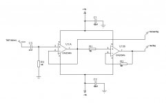
SEE NEXT POST FOR CORRECT SCHEMATIC. (unable to modify the one on this post for some reason.)


I am designing a circuit where I need to buffer some audio, outputting both an in phase as well as an inverted signal. The stage after this adds a lot of gain, so I need to get the noise floor as low as possible.
I used an opa2134 because it's a high quality audio opamp, with low noise and distortion figures.
Attached is the schematic as well as FFT grabs of the two outputs. Running a -50dbfs 1k test tone. For the initial buffer, I used a basic unity gain buffer. This output is great, the noise floor is about as good as a monster cable in this configuration.
The Inverting buffer is as basic as you could get, using the second opamp on the same chip. There is a 60hz hum+harmonics at least 25db louder than the nonInverting buffer. Can anyone explain why???
I tried changing the 10k resistors on the inverting stage to 1k, 500ohm and 100k. The behavior was about the same. A tiny bit of noise with the 100k's but still much quieter than the 60hz and it's harmonics.
I tried different dual opamp chips, and tried swapping the on-die opamps. I tried this on a PCB first, with ground planes, again without ground planes (star grounding), then on a breadboard. Same results. Lead length and circuit orientation don't seem to change anything. Tried more than 100nF decoupling caps, and the coupling caps are as close to the pins as possible.
Pretty weirded out by this. Thanks for your thoughts!
SEE NEXT POST FOR CORRECT SCHEMATIC. (unable to modify the one on this post for some reason.)
Attachments
Last edited:
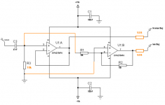
Here is the correct schematic, the one above is wrong. I re-drew it from a bigger design and made a second noninverting, when it is indeed a noninverting followed by an inverting.
Attachments
Last edited:
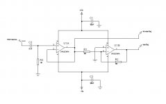
Hi, wierd ! It sounds like you're getting 60Hz injected through your common/ground track/s. Try rerouting as in my screenie. I also made a few other changes for the better 😉
Thanks ZeroD,
I think I'm making some progress on this.
The grounding I'm using is a star ground, so I'm pretty confident about the grounding scheme.
If I change that 1M to 10k, the RC filter changes and I'd lose all the bass, plus it would load the previous stage too heavily. I need a 1M input impedance or higher. Since there's no hum after the first stage I doubt that's the issue.
Running the two stages in parallel is also not possible, because there would be 20K impedance to the output of the second opamp, messing(essentially in parallel) with that 1M input impedance, so not possible without changing the other two resistors to a very high value, adding hiss to the circuit.
As far as the output resistors I'm actually doing that in the next stage, lol. Just didn't draw it, because it's not relevant to the noise.
------
On Another Note! I WAS able to get rid of the noise using 9v batteries instead of the power supply!!!
Something about the power supply is injecting a 60hz hum. I've been trying various RC filters and bigger decoupling caps to filter it out but to no avail yet....
hmmmmmm......
If I change that 1M to 10k, the RC filter changes and I'd lose all the bass,
Not if that input cap is 47uf ? I couldn't read it clearly ! Anyway 10uf would be more than enough to not lose ANY bass.
plus it would load the previous stage too heavily.
Really ! What are you driving it with ?
Since there's no hum after the first stage I doubt that's the issue.
That wasn't for the hum issue, just to improve it.
Running the two stages in parallel is also not possible, because there would be 20K impedance to the output of the second opamp,
How do you arrive at that ?
Apart from the other things, try moving the Inv + Input to where i showed & see if that makes a difference on it's own. The fact that batteries changes things, means that you DO have a common/ground loop issue. And/or getting 60Hz injected from the bypass caps, so move those common returns Directly to the star point on the pcb.
Last edited:
<< Something about the power supply is injecting a 60hz hum. I've been trying various RC filters and bigger decoupling caps to filter it out but to no avail yet.... >>
Are you using a wall wart? In my experience some of them just flat won't work, while others will, go figure.
Are you using a wall wart? In my experience some of them just flat won't work, while others will, go figure.
Not if that input cap is 47uf ? I couldn't read it clearly ! Anyway 10uf would be more than enough to not lose ANY bass.
Really ! What are you driving it with ?
That wasn't for the hum issue, just to improve it.
How do you arrive at that ?
Apart from the other things, try moving the Inv + Input to where i showed & see if that makes a difference on it's own. The fact that batteries changes things, means that you DO have a common/ground loop issue. And/or getting 60Hz injected from the bypass caps, so move those common returns Directly to the star point on the pcb.
I have the label on that cap wrong, it's 47nF!! oops. Misunderstanding there.
I'm driving it with a passive instrument pickup, 1M is the standard input impedance of a guitar or bass. Piezo based instruments are actually better with 4.7M or 10M inputs (acoustic guitar or mandolin). Also there is a mode where it is driven by a vacuum tube stage (220k output impedance). Regardless, the spec for this design requires 1M input impedance.
The path through R1 and R2 would arrive at the very low output impedance node of the opamp U1:B (essentially ground). The input impedance of a noninverting stage is close (as is reasonable possible) to infinity. The input impedance of an inverting stage is essentially the two resistors added together.
The + of the inverting is tied to the same ground point as the 1M is. It's been star grounded the whole time, so all ground connections are at the same point. I can't imagine there being any loops in this case at all.
This problem is sooo weird.
<< Something about the power supply is injecting a 60hz hum. I've been trying various RC filters and bigger decoupling caps to filter it out but to no avail yet.... >>
Are you using a wall wart? In my experience some of them just flat won't work, while others will, go figure.
Nope, using a linear transformer based supply. Two 18v AC windings, measuring 27v DC unregulated. Dual bridge rectifiers, 10000uF caps, 7815 and 7915 regulators. In a separate shielded enclosure.
I have the label on that cap wrong, it's 47nF!! oops. Misunderstanding there.
OK.
I'm driving it with a passive instrument pickup
Ahh, now i know, i understand why you need the high impedance input on U1A.
Have you checked to see if there are any whiskers of solder across any common/ground tracks ?
As an aside, you didn't need to go for an 18-0-18 TFR, a 15-0-15 would have been fine, unless you were serverely loading it. Better dissipation for the Regs too.
Hope you get it sorted, keep us posted.
Is this a DI? Why use (2) opamps? You can just use a single opamp (in buffer configuration) for the interface to the guitar. Then if you want balanced out, you can use a THAT 1646 balanced driver hanging on the output of the OPA2134 opamp. (Might as well use an OPA134).
PS: If using a 1646, you also gain an additional +6dB output on your balanced out. Nice signal to feed into another preamp or audio interface.
Re: PSU. 7915/7815 are noisier than LM317/337 regulators. But that shouldn't be related to your hum problem. My guess is your star grounding is the culprit. Is this on a breadboard? or PCB? If breadboard, expect hum. Make a proper PCB.
I've made a similar circuit and just used a double-sided PCB, with ground planes on top and bottom. Very quiet, no hum even with a guitar connected to it.
You need to protect from RFI pickup on the inputs. As is, your ckt above is susceptible.
Is this a DI? Why use (2) opamps? You can just use a single opamp (in buffer configuration) for the interface to the guitar. Then if you want balanced out, you can use a THAT 1646 balanced driver hanging on the output of the OPA2134 opamp. (Might as well use an OPA134).
PS: If using a 1646, you also gain an additional +6dB output on your balanced out. Nice signal to feed into another preamp or audio interface.
Re: PSU. 7915/7815 are noisier than LM317/337 regulators. But that shouldn't be related to your hum problem. My guess is your star grounding is the culprit. Is this on a breadboard? or PCB? If breadboard, expect hum. Make a proper PCB.
I've made a similar circuit and just used a double-sided PCB, with ground planes on top and bottom. Very quiet, no hum even with a guitar connected to it.
You need to protect from RFI pickup on the inputs. As is, your ckt above is susceptible.
No, not a DI. This is a small part of a much bigger device. It is possible for an instrument to be connected to this point, but not always. The first buffer stage is working perfectly as needed.
The regulator noise is not an issue. The 60hz (and harmonics) is. The PSRR on the opamps make the tiny bit of regulator noise far below what is needed.
In my first post I mentioned that I have built this on two different PCB layouts. First with a ground plane, second with a star ground. Ive built it about 4 different ways on a breadboard now and all three have identical results. Layout is not the issue.
Yes, RFI is dealt with. The entire diagram is not here, and in the full design I have ferrite beads on the instrument inputs, followed by a relay. I'm not having an issue with RFI, just the 60hz on the inverting buffer and I'm isolating this tiny piece of the circuit to try an isolate why.
Here's what I've done so far:
I've tried 3 different "low noise" opamps plus several others. Burrbrown, 5532, Tl074
I've tried two different power supplies.
I've tried ceramic, poly, and electrolytic decoupling caps. Ranging from 100nF to 10000uF is various combinations.
My power rails have NO ripple (it's below the thermal noise floor of the regulators).
Everything is grounded to one point.
I've tried metal film as well as 1/2watt carbon comp resistors.
The output of the noninverting stage is PERFECT. Same as a wire to my interface.
Tried 20ohm resistor with 10000uF caps on the power rails, (lowpass filter at .8hz). This makes the thermal noise on the power rails unmeasurable on my oscilloscope- perfect flat line).
Shielding inside a 1/8" aluminum enclosure does nothing.
Using batteries is the only way I've seen the hum go away (unfortunately not an option in this project).
Ok, I got it figured out!
It WAS a ground loop. I powered off batteries (no hum), then connected the ground of my PSU to the circuit, and the hum came back. There was a loop between the power supply and the interface I was using to get an FFT of the test signal.
Thanks everyone for your help!
It WAS a ground loop. I powered off batteries (no hum), then connected the ground of my PSU to the circuit, and the hum came back. There was a loop between the power supply and the interface I was using to get an FFT of the test signal.
Thanks everyone for your help!
- Status
- Not open for further replies.
- Home
- Source & Line
- Analog Line Level
- Basic Inverting Opamp HUM