Hi,
I'm playing with gsmok's simulator, it's an extremely useful tool, and it gives a lot of fun too.
Well, I'm trying to found some good operating point for the modest ECC81 tube,
I set generous 400V B+ and the forum recommended 200V on the plate. I'm also keeping an eye on vgk to be -2v or higher,
but I'm having a hard time to nail one with THD levels less than 2 to 3%.
Unless that famous "sweet spot" is all about the extremely low level of 3hd that you can hit using these parameters...?
Using a 2mA CCC plate load and a red LED for biasing the cathode, I was able to get better than 0.05% distortion at about 10V out.
Yes, a constant-current plate load can give very low distortion because the tube is loaded only by its own plate resistance, and the nonlinearity of plate resistance cancels the nonlinearity of gm.
This is all good until you load it by driving a following stage. 🙂
This is all good until you load it by driving a following stage. 🙂
Presumably, the following stage has a reasonable high impedance (~470k-1M) if it's being driven by a voltage amp. If not, well, that's why the cathode follower was invented.
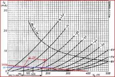
A definite sweet spot for the 12AT7/ECC81 is 200-220 V. on the plate and an IB of 3 mA. A net load of at least 3X RP is in order.
A resistively loaded 'T7 section in the small signal circuitry of a PP amp is highly synergistic. Look at the OVERALL harmonic distortion distribution, for the unit.
A resistively loaded 'T7 section in the small signal circuitry of a PP amp is highly synergistic. Look at the OVERALL harmonic distortion distribution, for the unit.
I understand that we are talking 2 to 3 ma at idle
I understand that as part of a whole amplifier circuit is one thing, and to try to minimize THD as isolated voltage amplifier is another.
I'm trying the second thing, and I can drop from 2 to 3% thd (according to the simulator). Perhaps a look to the MJ book to learn how to compute THD with calculator paper and pencil is in order, but I'm too lazy 🙂)
I can notI'm trying the second thing, and I can drop from 2 to 3% thd (according to the simulator).
Yes , I suppose that a real 12AT7 (better a bunch of them, of different brands) tested on an actual circuit, is the way to go
You can get a rough idea from the curves or sims, but in reality, you have to measure.
Remember that in a triode, THD is proportional to output level, so unless you state the output level, we have no way of knowing if your results are good or bad.
Cheers
Ian
Remember that in a triode, THD is proportional to output level, so unless you state the output level, we have no way of knowing if your results are good or bad.
Using a 2mA CCC plate load and a red LED for biasing the cathode, I was able to get better than 0.05% distortion at about 10V out.
Bolded for easier comprehension.
Ian, SY: it was under my nose all the time.
The simulator displays the % THD for a given input
So, in this case, if I set 1vin the result is for input times mu.
Under this perspective, the results are Ok, and so is for the suggested operating points.
Many thanks
Cheers
J.
The simulator displays the % THD for a given input
So, in this case, if I set 1vin the result is for input times mu.
Under this perspective, the results are Ok, and so is for the suggested operating points.
Many thanks
Cheers
J.
Ian, SY: it was under my nose all the time.
The simulator displays the % THD for a given input
So, in this case, if I set 1vin the result is for input times mu.
Under this perspective, the results are Ok, and so is for the suggested operating points.
Many thanks
Cheers
J.
I think you need a better simulator. Try LTSpice which will show the output level and the distortion.
Cheers
Ian
- Status
- Not open for further replies.
- Home
- Amplifiers
- Tubes / Valves
- ECC81/12AT7 "sweet spot"