Slightly off topic but I've been waiting 2 months for Tent Regs and no replies to e mails........not good!
In contrast Belleson got me the goods in the UK almost before I'd placed the order, arriving in 24 hours!
In contrast Belleson got me the goods in the UK almost before I'd placed the order, arriving in 24 hours!
Does the newer mainboard not need this /already have this mod then?
David
Nope.
2-Chip 1/2 Clock Delay - Recommended! response
Carlsor,
I would be very interested in what you are proposing.
Especially if you will install the surface mount chips.
I would additionally be interested in buying the thing "made" if that might be an option.
Hoe many of would need to subscribe for this to be worth your while?
Thanks for the offer and the work.
small film capacitor across the output
aside from what Zen Mod said, these may also help filter out the HF artifacts an NOS/NDF DAC may pass through. These can be pretty weighty, especially if one has a very wide bandwidth system.
Radu.
Last edited:
2SK246Y CCS HOLY GRAIL!
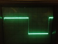
I put some 2SK246Y JFETS through my injected 10KHz 0.1V square wave signal tests on a scope.
The big square wave scope display is from the top (drain) of the JFET at 50mv/div. The JFETS were set up to have a voltage drop of 2.46V from Vd to the low potential end of the source resistor where it joined the jumper to the JFET gate. The signal then went through a 1000 ohm resistor to ground across which I could measure the ma and adjust the source resistance pot to measure .406V (.406ma). The Scope leads were placed across the 1000 ohm resister to measure the current regulating ability and transient response of each JFET.
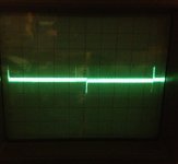
The next Scope pic is for a 2SK246Y (2.43ma Idss) set at 5mv/div. Current regulation is near perfect with the smallest transient response spikes I have ever seen from a JFET. Several 2SK246Y JFETS ranging from an Idss of 1.79ma to 2.70ma were tested. The Scope displays were identical. Of course the source resistance had to be changed to achieve the same 0.406ma.
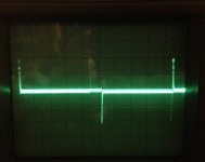
The right most Scope pic is for a 2SK170bl (7.47 Idss). This shows much larger spikes in response to the square wave.
Now to build some CCS boards with the 2SK246Y and begin the burnin process. I would be shocked if they didn't sound at least as good as the 2SK170. As I mentioned before, the 2SK246Y is very temperature stable in the 25-40C range. This appears to be the Holy Grail of JFETs for the DDDAC!
The scope pics are dark because I had to turn off all the CFL lights at my work bench because they added noise to the display.
I put some 2SK246Y JFETS through my injected 10KHz 0.1V square wave signal tests on a scope.
The big square wave scope display is from the top (drain) of the JFET at 50mv/div. The JFETS were set up to have a voltage drop of 2.46V from Vd to the low potential end of the source resistor where it joined the jumper to the JFET gate. The signal then went through a 1000 ohm resistor to ground across which I could measure the ma and adjust the source resistance pot to measure .406V (.406ma). The Scope leads were placed across the 1000 ohm resister to measure the current regulating ability and transient response of each JFET.
The next Scope pic is for a 2SK246Y (2.43ma Idss) set at 5mv/div. Current regulation is near perfect with the smallest transient response spikes I have ever seen from a JFET. Several 2SK246Y JFETS ranging from an Idss of 1.79ma to 2.70ma were tested. The Scope displays were identical. Of course the source resistance had to be changed to achieve the same 0.406ma.
The right most Scope pic is for a 2SK170bl (7.47 Idss). This shows much larger spikes in response to the square wave.
Now to build some CCS boards with the 2SK246Y and begin the burnin process. I would be shocked if they didn't sound at least as good as the 2SK170. As I mentioned before, the 2SK246Y is very temperature stable in the 25-40C range. This appears to be the Holy Grail of JFETs for the DDDAC!
The scope pics are dark because I had to turn off all the CFL lights at my work bench because they added noise to the display.
Attachments
Excellent work! Thanks for the pictures. I've had the bits here to do the modification for a few days but haven't sat down to work out what goes where. I think that's all pretty clear from your pictures. Brilliant 🙂It works! See pictures below. Took about 4 hours total to build and install.
Certainly sounds a worthwhile addition 🙂
And the 2sk246y results look very promising too. I've had 4 arrive here this morning. Need to see how they measure and work out what resistors I'm going to need.
Tweak board sounds like a cool idea 🙂
Last edited:
Quick question: I have 120r I/V resistors rather than the recommended 133r, just due to availability of the rhopoint resistors I've used. I believe this makes my output quieter, but can anyone tell me by how much?
I have some new amps with a passive preamp and it's a little on the quiet side, so anywhere I can get an extra bit of gain back is worthwhile...
I have some new amps with a passive preamp and it's a little on the quiet side, so anywhere I can get an extra bit of gain back is worthwhile...
Great effort, can you draw us a little diagram of what you did at some point?
The next Scope pic is for a 2SK246Y (2.43ma Idss) set at 5mv/div.
That's pretty impressive carlsor.
I bet you found something special.
Doede, since you've hinted at possibility of a new board. I came across a mention of the DSD1794A, seems to be virtually equivalent to the PCM1794A, but with the additional support for DSD. Should be intresting.
Also would there be milage in exposing pin 7 for an external clock source?
Also would there be milage in exposing pin 7 for an external clock source?
= 0,89dB...
Thanks guys.(120/133) x 100 - 100 [%]
= -9.77%

The Rhopoint resistors I've used are only available to 10r steps. Would I get distortion if I used 140r for a single deck? Or 135r?
My amps have an input sensitivity of 1.5v and not much gain, so the more I can get out of the DDDAC, the better
Hi
It looks there's some good tweaks to be done here. I like the idea of adding the 1/2 clock cycle delay to bring my old main board up to the latest spec. I have a question regarding the main board voltage regulator, can the 3.3V unit be directly replaced by a 5V unit? If so is there a benefit of fitting a belleson as Carlsor mentions?
It looks there's some good tweaks to be done here. I like the idea of adding the 1/2 clock cycle delay to bring my old main board up to the latest spec. I have a question regarding the main board voltage regulator, can the 3.3V unit be directly replaced by a 5V unit? If so is there a benefit of fitting a belleson as Carlsor mentions?
No question the additional logic chips are necessary can be run at 3.3 or 5vHi
It looks there's some good tweaks to be done here. I like the idea of adding the 1/2 clock cycle delay to bring my old main board up to the latest spec. I have a question regarding the main board voltage regulator, can the 3.3V unit be directly replaced by a 5V unit? If so is there a benefit of fitting a belleson as Carlsor mentions?
- Home
- Source & Line
- Digital Line Level
- A NOS 192/24 DAC with the PCM1794 (and WaveIO USB input)