Are you comparing 1 deck capless pos+neg output to a 4 deck with output caps?
No, I'm comparing I deck cap less pos + neg output to 4 deck in same format. We all know now high a reg on the analogue v+ improves the SQ but I'm surprised by how much the addition of an Elna Silmic makes and also a larger choke on the 8v regulator
No, I'm comparing I deck cap less pos + neg output to 4 deck in same format. We all know now high a reg on the analogue v+ improves the SQ but I'm surprised by how much the addition of an Elna Silmic makes and also a larger choke on the 8v regulator
@stijn001: with reference to post 2983
Hi - thanks for your question - a bit late reply from me as I currently are doing other things, but yes, I am using my own circuitboard with an - as much as I could - optimized layout with respect to low impedance decoupling paths, isolating the digital noise and low & symmetrical jitter for the two channels.
Now I also have gotten around to connecting the batteries and am slowly starting to find out what the DAC is like & enjoy the music ...
Cheers,
Jesper
Excellent data and intresting approach. Quite a sidestep from what others have been doing.
What do you mean with "inspired", did you use your own circuitboard?
Hi - thanks for your question - a bit late reply from me as I currently are doing other things, but yes, I am using my own circuitboard with an - as much as I could - optimized layout with respect to low impedance decoupling paths, isolating the digital noise and low & symmetrical jitter for the two channels.
Now I also have gotten around to connecting the batteries and am slowly starting to find out what the DAC is like & enjoy the music ...
Cheers,
Jesper
dwjames: "Looks like the LT3092 doesn't have one of those, so worth keeping that in the list of possible solutions. On the subject of LT3092, I notice that in the datasheet, there is an example layout for a high accuracy application using a diode instead of one of the resistors, but unless I missed something, that particular setup isn't covered in the text there. Anyone care to comment?"
I should be receiving 4 of these on Monday. We only have about 2.45V from pin 20 to ground so we can't use up 1.25Vof this in the voltage regulating resistors part of the circuit. I plan to use 18-20K adjustable resistance on the left side and a 470ohm fixed resister on the right side for a 0.188 voltage drop at 0.4ma. The LT3092 device will have about 2.26V to work with. It will be interesting how the scope display for this compares with other circuits I have tested. I should also be getting ten 2SK246 JFETS on Monday. The fun never stops.
No doubt that device is worth exploration - even though I am more excited about the "Borbely" FET - I am embarrassed that I am not able to participate in this the proper way. I keep changing what I want to do with the DAC board - more on this below.
My only caveat is that the OP AMP within the "new" current source chip will definitely contain silicon capacitors. (just realized I had been placing an "e" after silicon - very different substance; embarrassing)
Latest change is based upon nige2000's BRILLIANT powering idea - first I was going with this to power the computer I will be using as a transport. I asked Nigel if he thought this approach would work with the DAC and, of course, it will since he is already doing this.
His idea is so elegant - using the A123 large cells he puts together the number of cells required - in this case one for the 3.3 V and three for the 8 volts. He uses a small power supply that acts as a charger set to the voltage required. The batteries will not go over this voltage. He leaves the supply on while using the DAC, or computer transport, - he has found a source for a very inexpensive but better than decent, ready to go, other than power transformer, adjustable power supply. He has told me that he hears no influence from the supply since he hears nothing different when it is OFF. I wonder if a small resistor on the output of these regs would offer a little extra islolation, he seems to think it is unnecessary.
The trick will be turning it on and off. I was hoping I could leave it running all of the time and I am waiting for him to tell me his misgivings about this. I hate the thought of placing a switch contact between the battery and the PCM1794.
BUT still, there will be nothing needed on the PCB. None of the through hole components are needed but of course one still needs to rid the board of the standard regulators. (Of course, the wiring to the motherboard must be retained!)
He has found placing a regulator after the battery/batteries spoils the sound.
I figure the batteries can be placed underneath the board - but I am waiting for them to arrive since I have no real idea of their size (I can read the measurements but until you have them in hand ...).
I think this is about the neatest thing I have heard in a long time for powering low voltage circuits.
The A123 batteries are extremely low ESR - they are acting as a giant cap bank with much less "lag" than a cap bank ever could.
They are not cheap but then not ridiculous either. (about nine dollars each)
Other than the on/off switching the other problem to solve is welding tabs to the battery's ends. There is a battery shop near me that I hope will do this for me. You can solder them but you can also ruin them by soldering them.
nige2000 writes about his explorations at TIR NA - the thread that contains most of his insights - Tír Na HiFi • View topic - AUDIO PC: Direct power to motherboad 24 and 4pin (picoless).
You can also read about mqn player at this site. Lots of good information there - many fine tinkerers at this site - very impressive, very "hands on".
I am getting my batteries from here: A123 Systems Cells and Battery Modules
I think you should just use the large cells.
This is a very important idea. I look forward to telling you more as I can.
Hi guys. One simple question. Is it ok to use the Cinemag transformers with only one dac deck ? With the Sowters it's recommended to use 4 decks to achieve the needed low output impedance I'm almost ready to push the "buy" button and not shure if I will go for 1 or 4 dac decks.
Just as I am writing now, music plays in the background through Buffalo IIISE dual-mono. It sounds very good, but the Nos 1794 dac and the great feedback it receive everywhere makes me want to give it a try. First start with one deck just to hear the potentional and eventually, if it suit my taste, go all the way with 4 or 8 decks and bigger trafo's etc etc,,
Just as I am writing now, music plays in the background through Buffalo IIISE dual-mono. It sounds very good, but the Nos 1794 dac and the great feedback it receive everywhere makes me want to give it a try. First start with one deck just to hear the potentional and eventually, if it suit my taste, go all the way with 4 or 8 decks and bigger trafo's etc etc,,
Last edited:
No doubt that device is worth exploration - even though I am more excited about the "Borbely" FET - I am embarrassed that I am not able to participate in this the proper way. I keep changing what I want to do with the DAC board - more on this below.
My only caveat is that the OP AMP within the "new" current source chip will definitely contain silicon capacitors. (just realized I had been placing an "e" after silicon - very different substance; embarrassing)
Latest change is based upon nige2000's BRILLIANT powering idea - first I was going with this to power the computer I will be using as a transport. I asked Nigel if he thought this approach would work with the DAC and, of course, it will since he is already doing this.
His idea is so elegant - using the A123 large cells he puts together the number of cells required - in this case one for the 3.3 V and three for the 8 volts. He uses a small power supply that acts as a charger set to the voltage required. The batteries will not go over this voltage. He leaves the supply on while using the DAC, or computer transport, - he has found a source for a very inexpensive but better than decent, ready to go, other than power transformer, adjustable power supply. He has told me that he hears no influence from the supply since he hears nothing different when it is OFF. I wonder if a small resistor on the output of these regs would offer a little extra islolation, he seems to think it is unnecessary.
The trick will be turning it on and off. I was hoping I could leave it running all of the time and I am waiting for him to tell me his misgivings about this. I hate the thought of placing a switch contact between the battery and the PCM1794.
BUT still, there will be nothing needed on the PCB. None of the through hole components are needed but of course one still needs to rid the board of the standard regulators. (Of course, the wiring to the motherboard must be retained!)
He has found placing a regulator after the battery/batteries spoils the sound.
I figure the batteries can be placed underneath the board - but I am waiting for them to arrive since I have no real idea of their size (I can read the measurements but until you have them in hand ...).
I think this is about the neatest thing I have heard in a long time for powering low voltage circuits.
The A123 batteries are extremely low ESR - they are acting as a giant cap bank with much less "lag" than a cap bank ever could.
They are not cheap but then not ridiculous either. (about nine dollars each)
Other than the on/off switching the other problem to solve is welding tabs to the battery's ends. There is a battery shop near me that I hope will do this for me. You can solder them but you can also ruin them by soldering them.
nige2000 writes about his explorations at TIR NA - the thread that contains most of his insights - Tír Na HiFi • View topic - AUDIO PC: Direct power to motherboad 24 and 4pin (picoless).
You can also read about mqn player at this site. Lots of good information there - many fine tinkerers at this site - very impressive, very "hands on".
I am getting my batteries from here: A123 Systems Cells and Battery Modules
I think you should just use the large cells.
This is a very important idea. I look forward to telling you more as I can.
The idea of using LiFePO4 cells on constant trickel charge is used by John Kenny with his Dac32 and Ciunas Dacs. Having owned both, I found that the DDDac easily beats both in SQ in standard form. Also LiFePO4 has been shown to produce some noise and SQ with the Kenny Dacs could be improved with some small digital chokes, OSCONs on the digital side and Black Gates on the analogue side. Of course the Kenny Dacs use different Dac chips.
David
Yes, it's fine to run Cinemags on a single deck. They'll perform better if you have more decks or a buffer output stage inbetween the dddac and the cinemags, but the sound quality from a single deck with cinemags is generally very good.Hi guys. One simple question. Is it ok to use the Cinemag transformers with only one dac deck ? With the Sowters it's recommended to use 4 decks to achieve the needed low output impedance I'm almost ready to push the "buy" button and not shure if I will go for 1 or 4 dac decks.
Just as I am writing now, music plays in the background through Buffalo IIISE dual-mono. It sounds very good, but the Nos 1794 dac and the great feedback it receive everywhere makes me want to give it a try. First start with one deck just to hear the potentional and eventually, if it suit my taste, go all the way with 4 or 8 decks and bigger trafo's etc etc,,
What's your amp setup though? Some people find that they can use the pos and neg outputs direct from the dddac without needing any coupling caps or transformers and this gives a wonderful sound for zero cost.
The 2 considerations for this are:
Handling the DC offset. There's usually minimal DC offset between pos and neg (like a few mV or so) which is easily taken care of if you have an amp with interstage transformers or coupling caps (as most valve amps do)
Then there's the grounding of the channels. On some amps the channel grounds are all joined together, whereas on others they're totally separate. Ideally you want an amp setup where these are separate if you want to retain the true original stereo separation, as you get channel bleed otherwise. Having said that, there are a few guys who run like this with a common ground between the channels and are happy with how it sounds.
Hope that helps,
James
Yes. The Cinemag transformer is 1:1 and less sensitive to a higher output impedance than the 1:2 Sowter. Check out DDDAC 1794 deel 5(Google translation) All the best, PerHi guys. One simple question. Is it ok to use the Cinemag transformers with only one dac deck ? ...
Yes, it's fine to run Cinemags on a single deck. They'll perform better if you have more decks or a buffer output stage inbetween the dddac and the cinemags, but the sound quality from a single deck with cinemags is generally very good.
What's your amp setup though? Some people find that they can use the pos and neg outputs direct from the dddac without needing any coupling caps or transformers and this gives a wonderful sound for zero cost.
The 2 considerations for this are:
Handling the DC offset. There's usually minimal DC offset between pos and neg (like a few mV or so) which is easily taken care of if you have an amp with interstage transformers or coupling caps (as most valve amps do)
Then there's the grounding of the channels. On some amps the channel grounds are all joined together, whereas on others they're totally separate. Ideally you want an amp setup where these are separate if you want to retain the true original stereo separation, as you get channel bleed otherwise. Having said that, there are a few guys who run like this with a common ground between the channels and are happy with how it sounds.
Hope that helps,
James
Hello James,
A little question about direct coupling the DDDAC with my amp, can I damage my amp with this setup, I have no idea if there is a coupling cap or interstage trafo in my amp ( a Harman Kardon 990), I know it is a double mono setup
Grtz
Martin
Yes! Start with one DAC
Yes! Start with one DAC and find out what upgrades in Vregs, PS, CCS, Rload resistors, capacitors, etc you like before you decide to "stack 'em up". The Buffer requires a +/-12 power supply and some SMD soldering on your part, but I might be able to help you with the Buffer if you send me a PM. The buffer provides a lower output impedance which makes the Cinemags sound more dynamic and detailed.
smooth dancer: "Hi guys. One simple question. Is it ok to use the Cinemag transformers with only one dac deck ?"
Yes! Start with one DAC and find out what upgrades in Vregs, PS, CCS, Rload resistors, capacitors, etc you like before you decide to "stack 'em up". The Buffer requires a +/-12 power supply and some SMD soldering on your part, but I might be able to help you with the Buffer if you send me a PM. The buffer provides a lower output impedance which makes the Cinemags sound more dynamic and detailed.
@charlyparker: There's a service manual - with schematic - for the HK990 here:
http://quality-and-performance.com/FILES/AUDIO-SERVICEMANUALS/HARMAN KARDON HK 990.pdf
Best regards,
Jesper
http://quality-and-performance.com/FILES/AUDIO-SERVICEMANUALS/HARMAN KARDON HK 990.pdf
Best regards,
Jesper
@charlyparker: There's a service manual - with schematic - for the HK990 here:
http://quality-and-performance.com/FILES/AUDIO-SERVICEMANUALS/HARMAN KARDON HK 990.pdf
Best regards,
Jesper
Thanks Jesper,
It looks very impressive to me, but my knowledge in this is very limited 🙂
I can't make any conclusion out of this, I see no cap or interstage trafo as far as I can see, but if it is so that there isn't any of this no cap or interstage trafo, can I do any harm to my amp when trying to connect the DDDAC direct to my amp.
For now I use Cinemag trafo with very nice result, but a little expirimenting to hear the difference between with or without the cinemag looks nice and simple, but not when damage my amp with it
Grtz
Martin
C49 is in the signal path, so DC is blocked.... This is at analog input
Ok I see now, C49 on Left and C52 on right , Thanks Doede
The idea of using LiFePO4 cells on constant trickel charge is used by John Kenny with his Dac32 and Ciunas Dacs. Having owned both, I found that the DDDac easily beats both in SQ in standard form. Also LiFePO4 has been shown to produce some noise and SQ with the Kenny Dacs could be improved with some small digital chokes, OSCONs on the digital side and Black Gates on the analogue side. Of course the Kenny Dacs use different Dac chips.
David
yes John Kenny has been using lifepo4 for many years, and i do own a cuinas
id be curious to see your reference on where "LiFePO4 has been shown to produce some noise"
however id highly disagree that the stock dddac is better than the ciunas
the cuinas may sound a little thinner by comparison but as far as noise floor dynamics and pure detail is concerned the cuinas is much superior
only when the 1794 chips got power direct from battery cells could it even challenge the cuinas
maybe we have different ideas on what is better
but at least ive tried the dddac in stock configuration and with direct lifepo4 supply
id be curious to see your reference on where "LiFePO4 has been shown to produce some noise"
Can't quote a precise source but around a year ago there were some measurements on the Web showing the noise profile of different batteries. LifePO4 had a noise profile so was certainly not silent, but was superior to lead acid.
As I hinted, with my own mods to Ciuanas and DAC32 showed there were gains to be had by sensible decoupling between the analogue and digital supplies which are simply lashed together on the original design.
however id highly disagree that the stock dddac is better than the ciunas
the cuinas may sound a little thinner by comparison but as far as noise floor dynamics and pure detail is concerned the cuinas is much superior
only when the 1794 chips got power direct from battery cells could it even challenge the cuinas
maybe we have different ideas on what is better
A good friend and I both replaced Ciunases with DDDacs and are happily convinced that a two or four board DDDac beat the Ciunas in dunamics, bass, solidity of image and detail. I did not compare a one board DDDac with the Ciunas but find a one board DDDac very satisfying in standard form apart from a few Elnas and Panasonic DC caps changed.
Excuse my enthusiasm for the battery supply - I am still enthused - what I am wanting to reassure is that I know one must STILL use a few components on the board! Just not that many ...
I had no idea if or who had put this into a commercial product but nonetheless think nige2000 deserves credit for putting it to use in DIY projects and letting others know what he has found. In this world of firsts for everything, no matter how minor, I think he deserves credit for finding that it can be done as a DIY-er. I do not think this is minor.
His first application was for powering a computer motherboard, the DAC came later, I would guess, as he found his way with the computer. Of course, powering a DAC is a simple operation compared to getting a computer to book with a non-standard PS. Sometimes the board does not care, sometimes it does.
Nonetheless, forgive my repetition, his thread at TIR NA has many good ideas within it and should be studied by those who are using a PC as a transport. The best part: if I, and others like me, do not bother him there are other things he is working on and he will be able to finish them if he does not have to answer too many questions!
there are a few using lifepo4 for this sort of thing
Red Wine Audio Components
its also good to know whom is providing the information because its usually more honest when its not from those with a vested interest see
Battery Power Supply | Battery vs Linear Power Supply | DAC Power Supply | Core Audio Technology
note their products
Core Audio Technology | Audiophile Power Supplies| Power Products | Power Conditioners | Grounding Cables | Grounding Station - Core Audio Technology
When Rick gets his dac in testing we will have a second opinion
More CCS Tests
LT3092, 2SK246, and mini-CCS boards came in today.
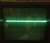
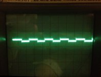
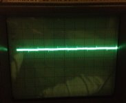
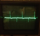
All tests performed with 10 KHz square wave at 0.1V RMS injected on top of the 2.45vdc "pin 20" simulated signal on my breadboard. All CCS circuits adjusted to 0.406ma. Scope display is 5mv/div.
The baseline scope picture is the simple 2SK170 CCS. This is my favorite sounding so far.
Next is the 2SK246 at 2.45V. Unfortunately Vgs had to be adjusted up to 1.85V in order to provide 0.406ma so the JFET has only 0.65V to regulate with. The datasheet shows 1.2V at O.4ma so I raised the "pin 20" voltage to 3.1 to give the 2SK246 1.2V to regulate with. This resulted in the best looking scope display yet. Heating up the 2SK246 with a rework heat gun only caused the current to drop only about 2%. If we can find some 2SK246 with a 1.2Vgs at 0.4ma this may be the best CCS yet. Maybe Erno can tell us where he got his.
I used the mini-board to build a LT3092 CCS. A heat gun did not cause the LT3092 to vary in current at all. Now the bad news - the scope display shows huge overshooting - even uglier looking than for the LM334. If there is interest I will build a second one and give it a listen. Anyone want to buy any LM334 or LT3092 parts?
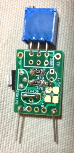
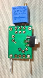
The CCS board was designed for a cascoded JFET and simple JFET but was able to accommodate the LT3092. The board can be installed many different ways with tall components installed on either side to fit into restricted spaces.
The 4th, 5th, and 6th pictures below are the ones referred to at the start of this post as the 1st, 2nd, and 3rd. You can figure out which one is the ugly one.
LT3092, 2SK246, and mini-CCS boards came in today.
All tests performed with 10 KHz square wave at 0.1V RMS injected on top of the 2.45vdc "pin 20" simulated signal on my breadboard. All CCS circuits adjusted to 0.406ma. Scope display is 5mv/div.
The baseline scope picture is the simple 2SK170 CCS. This is my favorite sounding so far.
Next is the 2SK246 at 2.45V. Unfortunately Vgs had to be adjusted up to 1.85V in order to provide 0.406ma so the JFET has only 0.65V to regulate with. The datasheet shows 1.2V at O.4ma so I raised the "pin 20" voltage to 3.1 to give the 2SK246 1.2V to regulate with. This resulted in the best looking scope display yet. Heating up the 2SK246 with a rework heat gun only caused the current to drop only about 2%. If we can find some 2SK246 with a 1.2Vgs at 0.4ma this may be the best CCS yet. Maybe Erno can tell us where he got his.
I used the mini-board to build a LT3092 CCS. A heat gun did not cause the LT3092 to vary in current at all. Now the bad news - the scope display shows huge overshooting - even uglier looking than for the LM334. If there is interest I will build a second one and give it a listen. Anyone want to buy any LM334 or LT3092 parts?
The CCS board was designed for a cascoded JFET and simple JFET but was able to accommodate the LT3092. The board can be installed many different ways with tall components installed on either side to fit into restricted spaces.
The 4th, 5th, and 6th pictures below are the ones referred to at the start of this post as the 1st, 2nd, and 3rd. You can figure out which one is the ugly one.
Attachments
Last edited:
Now the pictures are in the right place. Editing posts with pictures can end up with pictures in the wrong place or eliminate them - not much control over what happens.
That does look promisingLT3092, 2SK246, and mini-CCS boards came in today.
All tests performed with 10 KHz square wave at 0.1V RMS injected on top of the 2.45vdc "pin 20" simulated signal on my breadboard. All CCS circuits adjusted to 0.406ma. Scope display is 5mv/div.
The baseline scope picture is the simple 2SK170 CCS. This is my favorite sounding so far.
Next is the 2SK246 at 2.45V. Unfortunately Vgs had to be adjusted up to 1.85V in order to provide 0.406ma so the JFET has only 0.65V to regulate with. The datasheet shows 1.2V at O.4ma so I raised the "pin 20" voltage to 3.1 to give the 2SK246 1.2V to regulate with. This resulted in the best looking scope display yet. Heating up the 2SK246 with a rework heat gun only caused the current to drop only about 2%. If we can find some 2SK246 with a 1.2Vgs at 0.4ma this may be the best CCS yet. Maybe Erno can tell us where he got his.
I used the mini-board to build a LT3092 CCS. A heat gun did not cause the LT3092 to vary in current at all. Now the bad news - the scope display shows huge overshooting - even uglier looking than for the LM334. If there is interest I will build a second one and give it a listen. Anyone want to buy any LM334 or LT3092 parts?
The CCS board was designed for a cascoded JFET and simple JFET but was able to accommodate the LT3092. The board can be installed many different ways with tall components installed on either side to fit into restricted spaces.
The 4th, 5th, and 6th pictures below are the ones referred to at the start of this post as the 1st, 2nd, and 3rd. You can figure out which one is the ugly one.
Thanks for pushing ahead with the testing
- Home
- Source & Line
- Digital Line Level
- A NOS 192/24 DAC with the PCM1794 (and WaveIO USB input)