Hello!
I am looking for the YBDZ board schematic. Any help?
Thank you!
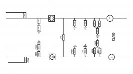
As far as I can tell the schematic is the same as the data sheet for the TPa311xd2. It is not the same as the EVM schematic. Ybdz also uses 22uH inductors and 10uF input SMT caps. All in all, a very nice sounding board even stock. I upgraded with OSCON SEPF caps and added bootstrap snubbers. The amp sounds fantastic now. I am thinking of order a couple more. Unlike the YJ blue black amp the Ybdz never gets warm. The inductors don't feel any warmer than room temp. The heatsinks maybe get a tiny but warm when using at high power levels but you can barely feel it. It might be that the stock inductors are quite good and not lossy.
Last edited:
I guess in a country known for selling replica Rolex watches and LV handbags it should not surprise is that fake premium components are being pushed on electronics. This is a country where there are people who will substitute phenolic powder for baby formula at the detriment of tens of thousands of babies who got sick drinking fake formula. But it will keep happening because we keep buying the cheap products at prices too good to be true.
Ok, so if we are not talking about quality of the parts used, WLX PCB seem to have a better implemetion of the chip than the SMSL SA-36A Pro?
By the way - here are some more detailed photos of the WLX TPA3116 board
New TPA3116 50W 50W 4ohm Class D Amplifier Kit | eBay
By the way - here are some more detailed photos of the WLX TPA3116 board
New TPA3116 50W 50W 4ohm Class D Amplifier Kit | eBay
Ok, so if we are not talking about quality of the parts used, WLX PCB seem to have a better implemetion of the chip than the SMSL SA-36A Pro?
By the way - here are some more detailed photos of the WLX TPA3116 board
New TPA3116 50W 50W 4ohm Class D Amplifier Kit | eBay
SMSL has pcb with all traces to all parts Texas Instruments EVM. WLX has not. SMSL is more complete copy.
Ok, so if we are not talking about quality of the parts used, WLX PCB seem to have a better implemetion of the chip than the SMSL SA-36A Pro?
By the way - here are some more detailed photos of the WLX TPA3116 board
New TPA3116 50W 50W 4ohm Class D Amplifier Kit | eBay
yeah, the WLX lacks the bootstrap snubber which is supposed to make a big difference. The SMSL has this already built in
Are you looking to get a board for modding purposes, or just working well out of the box?
What do you think?
Does it make a difference if it is
1) Bootstrap -> cap -> resistor -> ground
vs.
2) Bootstrap -> resistor -> cap-> ground
I've seen most the mods do it in 1) order?
Sure3116 has resistor->cap->ground
TI does cap->resistor->ground
Some say it won't make a difference, some say it does.
If it does Sure might have better sequence:
quote is taken out of context here!!
TI does cap->resistor->ground
Some say it won't make a difference, some say it does.
If it does Sure might have better sequence:
It DOES make a difference which way you wire them. At radio frequencies you would always place a physically large coil or capacitor with its outer layer connected to the earth plane.
This is to stop crosstalk and interference in the COMMON MODE. 😎
Whether it matters with the low frequencies and impedance of audio is debatable, but you might as well get it right. 🙂
quote is taken out of context here!!
Last edited:
Ok, so if we are not talking about quality of the parts used, WLX PCB seem to have a better implemetion of the chip than the SMSL SA-36A Pro?
By the way - here are some more detailed photos of the WLX TPA3116 board
New TPA3116 50W 50W 4ohm Class D Amplifier Kit | eBay
The film caps at the signal inputs are only 0.1uF Wima MKP10 caps. I'm not sure if you'll get much bass response. Most TPA31xx amps have at least 1.0uF caps. The SMSL SA-36A Pro has 3.3uF caps.
If the gain of the amp is set to 26dB, the Z (input) = 30kohms. Using the formula for cut-off frequency, 0.1uF for C (input) yields a cut-off frequency of 53Hz.
If the amp's gain is set to 20dB, the Z (input) = 60kohms. 0.1uF for C (input) yields a cut-off frequency of 26.5Hz.
Per the Texas Instruments TPA31xx technical data sheet:
Whether the caps are genuine Wima MKP10 film caps or not, this amp might be bass-challenged.🙁"If a flat bass response is required down to 20 Hz the recommended cut-off frequency is a tenth of that, 2 Hz."
Last edited:
The wima's bypass electrolytics (on input) on WLX
I can't tell from the photos, but that would make sense if that is the case.
😕YJ copied this AC1308, copied layout, just put values on silk like he does on other pcb's.
I thought the YJ board was designed by danz
😕
I thought the YJ board was designed by danz
Yep he copied that design from here and now also AC1308
http://www.taobao.com/view_image.php?spm=2013.1.0.0.sSVVbM&pic=Wx0GGlFDXA1VUwMAWx0SCwkNGRFcVxxQW1UcCxMFRBkDCFdVV1cRRhpWRF1DQg4MAgcHCQpdQltZX0JdF2ACYzonGiIRKi4qYGFqa2xgazZTS1tBGhBdWWxCHApdDhsL&title=VEnK%2FdfWuaa3xbDlIDUwVys1MFfLq8n5tcAvMTAwV7Wlyfm1wCEg0KHM5bv9o6y087mmwsoh&version=2&c=MmI4OTRkMWE3YzkyNjkwM2FlYzM2NDAxZTVmMDlkNTM%3D&itemId=36143080261&shopId=69692998&sellerRate=126&fv=9
http://www.taobao.com/view_image.ph...338614083&shopId=106750069&sellerRate=37&fv=9
Last edited:
Sure Boards PBTL?
I have just acquired one of the Sure boards for £12.72 off of ebay.
I plan to do the OSCON mod but has anyone made one of these boards PBTL?
Is the any quality degradation using the TPA3116 PBTL?
Regards Bern
I have just acquired one of the Sure boards for £12.72 off of ebay.
I plan to do the OSCON mod but has anyone made one of these boards PBTL?
Is the any quality degradation using the TPA3116 PBTL?
Regards Bern
I have just acquired one of the Sure boards for £12.72 off of ebay.
I plan to do the OSCON mod but has anyone made one of these boards PBTL?
Is the any quality degradation using the TPA3116 PBTL?
Regards Bern
There isn't quality degradation using the tpa3116 pbtl. But that does not mean the Sure3116 can be put into PBTL and work, or work with better or same quality. If you want outputfilter to be the same BTL and PBTL on Sure3116 you do need to do something with C7&C22, see drawing few posts back. You could remove them anyway also in BTL after you are familiar with Sure3116 sound, and/or replace the ceramic with film or something else. How much distortion can a 1nF ceramic add???
Will outputdiodes work in pbtl??? Input1 connected to ground close to chip might also do something to Sure circuitry, but you could ask Sure about PBTL for this ampboard.
Hi Irribeo,
Thanks for your reply, I have already sent an email to Sure and I am awaiting a reply.
Thanks Bern
Thanks for your reply, I have already sent an email to Sure and I am awaiting a reply.
Thanks Bern
Hi,
I've just done the OSCON mod, changing the six input caps for Panasonic SEPF 330uF 25v OSCON's on my Sure board.
Thank you very much xrk971 for suggesting this mod !
Even with using the poor power supply from my TV box the sound is VERY VERY good !!
It has inproved soundstage, the high section quality and the whole dynamic.
I coudn't connect another psu because i had no terminals left to connect the laptop PSU 19V/4.68 A (Dell model)
Last edited:
As far as I can tell the schematic is the same as the data sheet for the TPa311xd2. It is not the same as the EVM schematic. Ybdz also uses 22uH inductors and 10uF input SMT caps. All in all, a very nice sounding board even stock. I upgraded with OSCON SEPF caps and added bootstrap snubbers. The amp sounds fantastic now. I am thinking of order a couple more. Unlike the YJ blue black amp the Ybdz never gets warm. The inductors don't feel any warmer than room temp. The heatsinks maybe get a tiny but warm when using at high power levels but you can barely feel it. It might be that the stock inductors are quite good and not lossy.
Did you happen to take a pic of your bootstrap snubber mod on the Ybdz? If not, could you maybe give some verbal hints how to pull this off? It doesn't appear to be possible on the bottom of the board, but maybe I'm missing something?
Also, last night I received my Edcor transformers, and I was thinking about trying it out on the Ybdz board. But the transformers have balanced output, and I'm not 100% certain how to wire the balanced inputs.
Of course it's obvious where the + input of each channel goes, but... Looking at the board with the outputs on the right-hand side, and the inputs on the top: on the left hand edge of the board, middle group of SMD components (includes gain-setting resistors), looks like the top horizontally-oriented cap (in the group) is the one that bridges the negative side of one of the inputs (LIN- or RIN-) to ground. Does that sound right to you? If I've ID'ed the one negative input correctly, it means I've ID'ed the other one correctly as well.
Assuming I'm right, does that mean I have to solder a teeny tiny wire for - to one side of that cap solder pad, and another teeny tiny wire for GND to the other end of the tiny pad? And not accidentally short between the pads? Is there any reasonable way to give myself some more working room?
You first need to remove all input caps from the amp board, and then connect the balanced + and - leads from the input transformer secondaries to the solder pads directly connected to the corresponding TPA3116 amplifier IC inputs for LINP, LINN, RINP and RINN. You will also need to connect the transformer ground leads to the signal ground. You are right to avoid creating a solder bridge between the input cap pads.
Did you happen to take a pic of your bootstrap snubber mod on the Ybdz? If not, could you maybe give some verbal hints how to pull this off? It doesn't appear to be possible on the bottom of the board, but maybe I'm missing something?
Also, last night I received my Edcor transformers, and I was thinking about trying it out on the Ybdz board. But the transformers have balanced output, and I'm not 100% certain how to wire the balanced inputs.
Of course it's obvious where the + input of each channel goes, but... Looking at the board with the outputs on the right-hand side, and the inputs on the top: on the left hand edge of the board, middle group of SMD components (includes gain-setting resistors), looks like the top horizontally-oriented cap (in the group) is the one that bridges the negative side of one of the inputs (LIN- or RIN-) to ground. Does that sound right to you? If I've ID'ed the one negative input correctly, it means I've ID'ed the other one correctly as well.
Assuming I'm right, does that mean I have to solder a teeny tiny wire for - to one side of that cap solder pad, and another teeny tiny wire for GND to the other end of the tiny pad? And not accidentally short between the pads? Is there any reasonable way to give myself some more working room?
Posted this pic a while back.
http://www.diyaudio.com/forums/class-d/237086-tpa3116d2-amp-452.html#post4031693
I was also going to try a transformer on the YBDZ but decided it was too difficult to pick up the - input as you also observe. the blue/black would be a lot easier with its thru the hole caps. Actually you can see the mess I made with this in the pic above!
If you use balanced connections to amp surely any earth point will do rather than cramp yourself using the earth side of the - input cap?
Which Edcor did you buy?
Last edited:
- Home
- Amplifiers
- Class D
- TPA3116D2 Amp