Mate you are the magician, and you are the one that should teach us your tricks.
From the other hand there is a magic spell called as function generator, as soon you will disappear 300 EUR from your wallet, you will see it landing at your front door. 🙂
From the other hand there is a magic spell called as function generator, as soon you will disappear 300 EUR from your wallet, you will see it landing at your front door. 🙂
How to convert sine or square waves to sawtooth waves?
TIA
Felipe
Type eBay.com 😉
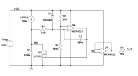
I slapped together a little sawtooth-wave generator on a scrap of perfboard, to help me figure out transformer winding polarities (also known as Winding Dots). It is powered from a little 5VDC wall wart adaptor, that I salvaged from an old "Wireless G" wifi router in the trash heap.
Since the circuit runs from single supply 5V, I selected a CMOS 5V rail-to-rail dual opamp from Microchip, the MCP6022 (data page), of which I have several dozen in my parts box. The first opamp is used as a comparator, and the second is used as a unity gain buffer, at lower right. 100 ohms in series prevents anything bad from happening if the output drives a very low impedance load, such as an accidental short circuit.
You can simulate this exact circuit in LTSPICE and watch it work; just substitute a Linear Technology 5V_RRIO opamp in the simulation. It needs to be CMOS because you overdrive the input pair by 2 volts; bipolars would melt. The LTC6081 appears to be a good choice.
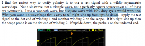
HOWEVER, months after I built this thing, I realized that any wildly asymmetric waveform would accomplish the same mission (transformer dot identification); the only requirement is that you be able to tell right-side-up from up-side-down. A square wave with duty cycle << 50% meets this criteria, and is waaaay easier to generate: just an NE555, 2 resistors, and 2 capacitors. D'oh!
Since the circuit runs from single supply 5V, I selected a CMOS 5V rail-to-rail dual opamp from Microchip, the MCP6022 (data page), of which I have several dozen in my parts box. The first opamp is used as a comparator, and the second is used as a unity gain buffer, at lower right. 100 ohms in series prevents anything bad from happening if the output drives a very low impedance load, such as an accidental short circuit.
You can simulate this exact circuit in LTSPICE and watch it work; just substitute a Linear Technology 5V_RRIO opamp in the simulation. It needs to be CMOS because you overdrive the input pair by 2 volts; bipolars would melt. The LTC6081 appears to be a good choice.
HOWEVER, months after I built this thing, I realized that any wildly asymmetric waveform would accomplish the same mission (transformer dot identification); the only requirement is that you be able to tell right-side-up from up-side-down. A square wave with duty cycle << 50% meets this criteria, and is waaaay easier to generate: just an NE555, 2 resistors, and 2 capacitors. D'oh!
Attachments
Hi Stuart, I don't think that's correct. I don't think the integral of a square wave is a sawtooth wave. Why not? Because the derivative of a sawtooth wave is certainly not a square wave. Rather, the derivative of a sawtooth is a constant (where the waveform is a ramp) plus a negative Dirac delta function, an impulse downwards (where the waveform is a step).Follow the square wave with an integrator.
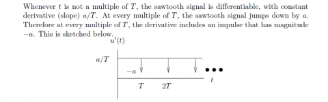
Stephen Boyd assigns this as a homework problem in his introductory circuits class at Stanford Univ: 3(d) In the space below, sketch the derivative of a sawtooth signal. Be sure to label all axes, slopes, magnitudes of any impulses, etc.
Here is his answer from the solution sheet (link):
![439847d1411417863-sine-square-waves-sawtooth-waves-stanford.png"]](https://www.diyaudio.com/forums/attachments/equipment-tools/439847d1411417863-sine-square-waves-sawtooth-waves-stanford.png"])
It's a constant (at a/T) plus a delta function of magnitude -a .
Probably what you meant was that a triangle wave is the integral of a square wave. However a triangle wave is symmetric, which may or may not fulfill the original poster's requirements.
Attachments
Last edited:
I failed to distinguish triangle from sawtooth. I will now go down to my special dungeon and receive lashes. 😀
Thanks, Mark!
Thanks, Mark!
You can simulate this exact circuit in LTSPICE and watch it work; just substitute a Linear Technology 5V_RRIO opamp in the simulation. It needs to be CMOS because you overdrive the input pair by 2 volts; bipolars would melt. The LTC6081 appears to be a good choice.
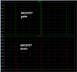
I tried this today and indeed it worked. However, Linear Technology's LT6081 dual opamp has a "sleep" pin (while my preferred 5V_RRIO device (the MCP6022) does not). So I simulated with its big brother instead, the LT6082 quad opamp -- four of the exact same CMOS 5V_RRIO opamps in a single package, but without a sleep pin to connect on the LTSPICE schematic. Whew!Here are a couple simulated waveforms. The comparator outputs a wee little "sliver pulse", just wide enough to pull the timing capacitor down to ground. Then the MOSFET shuts off and the LM334 current source starts charging up the capacitor again, on a delightfully linear ramp: dV/dt = I/C . I is constant, C is constant, thus dV/dt is constant, thus the ramp she is linear.
Attachments
Or is enough this 555 astable with a frequency of 1kHz and a mark to space ratio of 2:1
Attachments
Last edited:
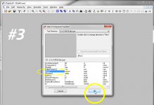
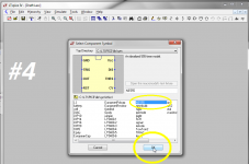
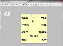
LTSPICE ships with a presupplied model of a 555 timer IC. It is found in the "misc" library, name NE555. This lets you run LTSPICE simulations of circuits that include 555 ICs.
LTSPICE ships with a presupplied model of a 555 timer IC. It is found in the "misc" library, name NE555.
look for the word "misc" in the images below.
_
Attachments


- Status
- Not open for further replies.
- Home
- Design & Build
- Equipment & Tools
- Sine or square waves to sawtooth waves