NDK ones are already in order and due in ~ 2wks time for the initial batch
There is one more left if you wish to order now. After this lead time is again 4-6wks
I would like to place order for NDK. How do I do that? Please PM.
For BUFF-II/IIIs with its own 100MHz clock in asynchronous mode it is best to use just a single CCHD 575 100MHz XO for the S03 board.
I see. Any reason not to use pn CCHD-950-25-100.000?
BK
I see. Any reason not to use pn CCHD-950-25-100.000?
BK
This is also good!
listening test of 90/98MHz VS 100MHz clock on ES9018?
Hi,,
Has anybody been making a listening test of the 90/98MHz Clock combination VS the 100MHz clock input on the ES9018 / Amanero ?
I like the theory of running even harm Clocks, which properly makes the ES9018 to sound better as the phase noise level of the clocks lowers when divided with 2 or 4 instead of having the PLL converting the 100MHz to usable sound format clock frequencies like 22,xxx and 24,xxx MHz rtc..
Please publish with links or comments..
Br
Caad
Hi,
is it that easy? PLL vs. frequency division? By what? Digital or mixing?
I do not believe... 😉
Cheers
is it that easy? PLL vs. frequency division? By what? Digital or mixing?
I do not believe... 😉
Cheers
Hi,
is it that easy? PLL vs. frequency division? By what? Digital or mixing?
I do not believe... 😉
Cheers
Hi,
Sorry i needed to also state that the I2S and the DAC will run in "sync mode" when using 90/98MHz.
br
Caad
For BUFF-II/IIIs with its own 100MHz clock in asynchronous mode it is best to use just a single CCHD 575 100MHz XO for the S03 board.
Assembly is nearly complete.
In the case of a single 100MHz XO, how do I handle R3 and R4? Any other things to do differently?
I have an early S03 board and an early Amanero. Presumably I should still follow your pdf pg5 modification notes?
BK
Assembly is nearly complete.
In the case of a single 100MHz XO, how do I handle R3 and R4? Any other things to do differently?
I have an early S03 board and an early Amanero. Presumably I should still follow your pdf pg5 modification notes?
BK
For Async reclocking as above:
X2 - 100MHz CCHD-950 XO
R3, R4 - NC
X1- NC
Also, if not mounted already:
U8, U5 and associated components like C16, C17, C13, FB4, R13 not needed
FB1 and C7 not needed
For Async reclocking as above:
X2 - 100MHz CCHD-950 XO
R3, R4 - NC
X1- NC
Also, if not mounted already:
U8, U5 and associated components like C16, C17, C13, FB4, R13 not needed
FB1 and C7 not needed
Perfect - thank you!
I have all the "extra" components mounted, so I will leave them in place for now.
Should I also disconnect 'CLK' to Amanero pin #7, and link pin #3 of U8 to Amanero pin #6 at this point, while access is easy?
BK
Perfect - thank you!
...
Should I also disconnect 'CLK' to Amanero pin #7, and link pin #3 of U8 to Amanero pin #6 at this point, while access is easy?
BK
Leave both pin#7 and Pin#6 of Amanero unconnected and not need to link pin3,U8. For this application Amanero does not require external clock (Master Mode) and DSDOE is not used for any signalling.
Last edited:
Leave both pin#7 and Pin#6 of Amanero unconnected and not need to link pin3,U8. For this application Amanero does not require external clock (Master Mode) and DSDOE is not used for any signalling.
Thanks again.
Here's the current status - still need to link K1. A few unnecessary parts for the current application, but I might change DACs in the future and reconfigure things. I'll yank pins 6 and 7 from the header.
The XO was challenging to solder with my smallest tip and the pad locations. Any tricks for this?
BK
An externally hosted image should be here but it was not working when we last tested it.
You populated both on-board regulators for the clocks, U1/Q1, U2, and their associated capacitors.
But you only need one of them.
Bridging links K1 or K2 will select which of them is used. But both will be powered via J1.
U1/Q1 looks to be a lower-noise (likely better) source than U2, so I'm planning to use it. Since you have them both on-board, I suggest you try it first with one chosen via K1 or K2, then the other, and see if you can hear any difference. If not, pick one to remove. If you hear a difference, keep the better.
My 2 cents for the day!
Greg in Mississippi
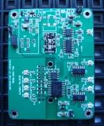
AKX9890NK Dual Sync Clock
Initial batch has arrived- 98.304MHz/90.3168MHz. Mounts in position X2
Doing some tests now. shipping soon...
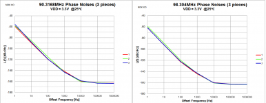
NDK XOs have been updated. Dual matched pair in a single 9x14mm package with select. Typical performance as shown. ... You will need only a single unit of this Dual XO for the S03 board ...
Initial batch has arrived- 98.304MHz/90.3168MHz. Mounts in position X2
Doing some tests now. shipping soon...
Attachments
Nice to see the clock selection circuit are going to build on a separate board
Can't wait to get the module
Can't wait to get the module
Initial batch has arrived- 98.304MHz/90.3168MHz. Mounts in position X2
Doing some tests now. shipping soon...
Nice to see the clock selection circuit are going to build on a separate board
Can't wait to get the module
Unfortunately , defects have been noted in the current batch
 Only 2 of the 5 samples received looked good during tests. The rest had various issues ranging from much higher than specified current consumption and not well formed outputs (logic levels and duty cycles). So will be returned to manufacturer for further inspection and advice. Not sure at this stage when it will be resolved. I will offer refund to those are affected shortly.
Last edited:
acko: why not send them back to NDK, and ask to get 3x new ones sent to you? (if they find them faulty).
acko: why not send them back to NDK, and ask to get 3x new ones sent to you? (if they find them faulty).
I was going to ask the same question.
I understand anything may goes wrong when it's a customized sample, but late is better than nothing
AKX9890-NDK Dual Clocks
Replacement and more samples are being built. They will be carefully tested at all stages of the production to ensure no duds. Factory lead time ~6-8wks. Hope those who are affected can wait this long. Please let me know if you have any concerns. Sorry for the inconvenience
Replacement and more samples are being built. They will be carefully tested at all stages of the production to ensure no duds. Factory lead time ~6-8wks. Hope those who are affected can wait this long. Please let me know if you have any concerns. Sorry for the inconvenience
Getting closer to integrating the Amanero/S03 for the first time and I want to achieve the best possible physical layout for my chassis.
The pic below is what I came up with. Anyone see a better way to lay things out?
I tried to keep the rectifiers and trafos to the edge and minimize I2S line length to/from the Otto. Will be using ufl connections wherever possible, in some cases terminating in cut ends. USB input will be panel mount cable.
From the lower right, the components are as follows:
- Placid HD-BP 2.1 @ +/- 13V (for Legato)
- LCDPS @ 5V (for USB power and ancillary components)
- Sigma-11 @ 5V (for Buff-II + three 5V S03 inputs)
- Amanero stacked with S03 with one 100MHz XO
- Otto-II
- 4:1 Mux
- Buff-II @ 100MHz with latest tridents and Legato 2
BK
An externally hosted image should be here but it was not working when we last tested it.
- Home
- Group Buys
- Amanero Isolator/Reclocker GB