No, not Ebay. From a shop here. Didn't pay attention while I was checking a few other component items in the list. Shop always provided original parts, but now...Ebay ?
I'll see if a get good sobstitutes later.

Replaced the drivers with MJE15032G/15033G and put multi-turn trimpots.
Sweeeeeeeet! 😎
Sweeeeeeeet! 😎
An externally hosted image should be here but it was not working when we last tested it.
It's doing fine! 🙂
In the PMA-757 there's a diode (??) "connected" to each PNP driver. Is it a current regulator?
In the PMA-757 there's a diode (??) "connected" to each PNP driver. Is it a current regulator?
An externally hosted image should be here but it was not working when we last tested it.
Could be a diode, it could be a thermistor. It will be for thermal compensation of the output stage. There may be other sensing too such as the vbe multiplier.
I have replaced the original relay as one channel (the left, iirc) was not connecting properly.
(below, 2nd picture with the contacts tarnished, I think)
Replaced with a new one and the full sound was back.
However, after a couple of weeks the right side started to "buzz" a bit, specially at low volume. Power caps are new, BTW...


(below, 2nd picture with the contacts tarnished, I think)
Replaced with a new one and the full sound was back.
However, after a couple of weeks the right side started to "buzz" a bit, specially at low volume. Power caps are new, BTW...
Buzz... as in ? 🙂
Low quiescent current can cause a buzzy sound (crossover distortion). I take it this one isn't the relay.
That's definitely one to scope and see what is happening.
Low quiescent current can cause a buzzy sound (crossover distortion). I take it this one isn't the relay.
That's definitely one to scope and see what is happening.
You're right, Mooly,Buzz... as in ? 🙂
Low quiescent current can cause a buzzy sound (crossover distortion). I take it this one isn't the relay.
That's definitely one to scope and see what is happening.
Buzzy sound on both channels. Not the relay itself. Might be indeed a crossover distortion.
I've also read somewhere about coil resistance and/or lower voltage, not enough to pull the armature.
Coil resistance in the newer Finder 41 relay is 1.44kohm and the original Matsushita has a 0.55kohm res value. How important is the coil resistance for relays?
..
Last edited:
Coil resistance is important to the electronics driving the relay. If there is a series dropper resistor then the voltages will all change with a different coil resistance. A low resistance will draw more current and could be beyond the driving transistor capability.
So, I was curious about another relay with same specs, including coil resistance.
Then I spent 6 Euros and bought an Omron with same numbers/parameters. Only thing is that the pin out is different, so I had to adapt it first for a test.
Frankly, I hear no distortion.
..
Then I spent 6 Euros and bought an Omron with same numbers/parameters. Only thing is that the pin out is different, so I had to adapt it first for a test.
Frankly, I hear no distortion.
An externally hosted image should be here but it was not working when we last tested it.
..
Last edited:
Karl and Mooly,
Only today I noticed that somobody actually replied to my post no. 1!
MJE transistors that are not marked as ON may be good and equivalent in parameters to the originals. Not necessarily fakes, but equivalents from another producer. There are Chinese manufacturers that produce first class equivalents. For instance, ISC (Inchange Semiconductors).
Original relay probably needed just cleaning of contacts. On my PMA737 one channel had intermittent contact. That problem was solved by opening the relay and cleaning the contacts.
So it looks as though it was another relay contact issue. Nice one 🙂
I think so. 🙂
The Omron is much more robust and has a nice starting "click" sound.


Karl and Mooly,
Only today I noticed that somobody actually replied to my post no. 1!
...
Original relay probably needed just cleaning of contacts. On my PMA737 one channel had intermittent contact. That problem was solved by opening the relay and cleaning the contacts.
Hi ivanlukic,
I believe you have the schematics at this point, but if not, I have it for you. 🙂
The tarnished contacts in the original relay had a hard layer of burnt stuff. 🙁 I used a small screw driver to remove it but it didn't come smooth and clean, so I decide to replace it, as a new relay is always good for the sound. 🙂
Cheers!


Ivanlukic,
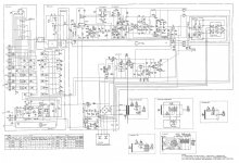
Attached below there is the entire schematics in one good JPG res.
The whole SM is in PDF file, but I couldn't upload it. You can dl easily from HiFi Engine:
Denon PMA-737 Manual - Stereo Integrated Amplifier - HiFi Engine
(I hope I'm not breaking any rules)
Edit: anyone confirm C33 and C34 (both 220uF 6.3V) are filters for the preamp? 🙂
..
Attachments
Last edited:
- Home
- Amplifiers
- Solid State
- Denon PMA 737 schematic needed