😎Very nice! I suppose with external power hookup you could run it on batteries...and with all those amps you could just wire the house for DC distribution...I'm jealous big hunks of clean smooth aluminum... it is porn!
Hi
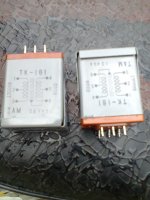
This is my first attempt at building an amp, i have 4 pairs of VFETS which i measured the Vgs for Ids of 1.5A with the following results :-
SK82 7.1,7.9,8.6 and 7.6 volts
SJ28 5.3,11.2,7.1 and 10.6 volts
can anyone tell me if there is any preference to the two pairs i use for the CSX1?
This is my first attempt at building an amp, i have 4 pairs of VFETS which i measured the Vgs for Ids of 1.5A with the following results :-
SK82 7.1,7.9,8.6 and 7.6 volts
SJ28 5.3,11.2,7.1 and 10.6 volts
can anyone tell me if there is any preference to the two pairs i use for the CSX1?
Hi
This is my first attempt at building an amp, i have 4 pairs of VFETS which i measured the Vgs for Ids of 1.5A with the following results :-
SK82 7.1,7.9,8.6 and 7.6 volts
SJ28 5.3,11.2,7.1 and 10.6 volts
can anyone tell me if there is any preference to the two pairs i use for the CSX1?
The 5.3 2SJ28 has a strange value compared to the rest, I wouldn't use that one.
I have 8 pairs but none is getting that low, they range from 8,9 - 11.8 Vgs @ 1.5 A.
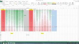
I promised to publish the measurements of my VFETs. See attachment. If somebody wants to swap, so we have both better matches, let me know 😀
Attachments
Last edited:
Quick question - is it more important to bias both channels to the same stable heat sink temperature or to the same bias voltage pot mV setting?
No, you bias till you have reached around 1.5 Ampere and the voltage at the speaker output is lowest.
No, you bias till you have reached around 1.5 Ampere and the voltage at the speaker output is lowest.
Thanks Walter.
I asked the question not knowing if biasing the VFETs in the CSX1 requires a different procedure than amps using "standard" transistors - which I bias so that both are at the linear part of the output devices within their SOA, and that is usually at the same temperature between channels. This can require quite different bias settings.
Exactly, the bias settings are very different.
Walter - you do mean "very different" between channels, right?
Ah, you meant between left and right channel ? I thought you meant bias of the P and N channel VFET.
Ah, you meant between left and right channel ? I thought you meant bias of the P and N channel VFET.
Yes, my question is "between left and right channels". How different are the bias currents on your VFET's between channels?
The bias current is 1.5 Ampere for each VFET in the left and right channel. The bias voltages needed to reach 1.5 Ampere are:
Left: 2sj28 9.3V , 2sk82 6.4V
Right: 2sj28 10.0V , 2sk82 7.8V
I used the worst matched VFETs that I have.
So I have better VFETs left over if I want to build a design with VFETs in parallel😀
Left: 2sj28 9.3V , 2sk82 6.4V
Right: 2sj28 10.0V , 2sk82 7.8V
I used the worst matched VFETs that I have.
So I have better VFETs left over if I want to build a design with VFETs in parallel😀
The bias current is 1.5 Ampere for each VFET in the left and right channel. The bias voltages needed to reach 1.5 Ampere are:
Left: 2sj28 9.3V , 2sk82 6.4V
Right: 2sj28 10.0V , 2sk82 7.8V
I used the worst matched VFETs that I have.
So I have better VFETs left over if I want to build a design with VFETs in parallel😀
Got it! Thanks, Walter! I am waiting for "Part 2" from Papa myself. Sitting on my restless hands is not so easy or fun.
I used the worst matched VFETs that I have.
So I have better VFETs left over if I want to build a design with VFETs in parallel😀
+1🙂
Attachments
- Status
- Not open for further replies.
- Home
- Amplifiers
- Pass Labs
- Article - Sony VFETs part 1