I can't think of anything obvious Salas but I think this is where the problem lies, the pot connections are:
Pot Tag(L) (R)
Output RCA linked grounds 1--wire link -- 1 DCB1 out GND
RCA signal out (left) 2 2 RCA signal out (right)
DCB1 out (left) 3 3 DCB1 out (right)
First attempt at adding a photo to a forum....
Pot Tag(L) (R)
Output RCA linked grounds 1--wire link -- 1 DCB1 out GND
RCA signal out (left) 2 2 RCA signal out (right)
DCB1 out (left) 3 3 DCB1 out (right)
First attempt at adding a photo to a forum....
Attachments
By the way I got the heatsinks here: Aluminum Heatsink Heat Sink & Isolation Kit TO-220 35 x 35 x 12.5mm Black - 4pcs
The DCB1 has been on all day 😡 at 200mV (level 1) and the sinks are just warm to the touch.
The DCB1 has been on all day 😡 at 200mV (level 1) and the sinks are just warm to the touch.
Pot must go between RCA in and DCB1 in.
Wired like this, and its metal body grounded also.
Wired like this, and its metal body grounded also.
An externally hosted image should be here but it was not working when we last tested it.
By the way I got the heatsinks here: Aluminum Heatsink Heat Sink & Isolation Kit TO-220 35 x 35 x 12.5mm Black - 4pcs
The DCB1 has been on all day 😡 at 200mV (level 1) and the sinks are just warm to the touch.
You mentioned "Vdrop across CCS (1.63v and 1.73v)" so there are 163 and 173 mA for sure if talking across 10 Ohm Rset CCS resistors. If the MOSFET itself is lukewarm too, its not bad heat transfer to the sinks, just those semis being too chunky to really care thermally at this level.
First attempt at adding a photo to a forum....
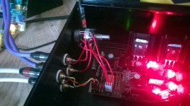
Red cable on RCA in common ground looks like not going to the center of the connector but to its left channel? Or its just the resolution bit grainy and I mix things.
Thanks Salas, that made me chuckle a bit. I'd put the pot in the wrong place! 😱 I swapped the molex plugs and re-wired the pot accordingly but instead of one clear channel and one very weak one I get the same overlayed by stacks of ground loop hum. Back to the drawing board...
Last edited:
Sorry about the mobile phone photos, on that picture the red goes to the middle GND molex pin.
Make sure that red gnd wire from RCA inputs common goes to pot circuit gnd and not some channel in. Also use nut and collar on the pot to fit a wire that grounds it.
the molex plugs
Try direct soldering to the PCB pins. Molex can be playing games at you.
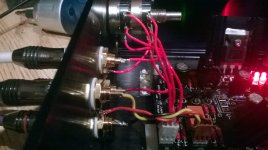
The pot's GND link is broken or just contacting the metal body? The white Molex's wires fit looks especially suspicious.
I snipped the wire connection between the stereo GND tags through desperation of trying every permutation of connections. I really appreciate your help mate. I've been at it all day so I'll call it a day and start afresh in the morning. Thanks again.
EDIT - sorry, I should have teased out those wires to make the picture a bit more meaningful!
EDIT - sorry, I should have teased out those wires to make the picture a bit more meaningful!
Last edited:
The new layout looks correct. See with direct soldering to pcb pins, restore the pot gnd link, and ground the pot's metal.
I found that the board Molex pins work well as points to solder the wires onto. I heatshrink them after soldering too. I hate all that beautiful precise circuitry undermined by crappy slide on clips and connectors.
That wiring is a mess.Yes, the molex connectors are a real pain, I'll try that. Here's the new (unsuccessful) layout...
Each channel should have a two wire, prefarably twisted pair going to the vol pot.
That output of the vol pot should also be a two wire connection, preferably twisted going to the input terminals of the board.
Repeat the two wire connections for the other channel.
The final wiring should have four (4) twisted pairs to/from the vol pot.
No single wires and no triple wires anywhere near the vol pot.
Where the wire ends are soldered to the sockets/vol pot/pcb try to minimise the AREA of the LOOPs between the Hot/Flow and the Cold/Return.
Last edited:
It certainly is Andrew! My plan was to test the circuit before starting again with everything cleaned up, heatshrink added etc. but the nest sort of grew. Even on the clean channel there's a very low level hum that could be sorted with twisted pairs. I'd seen advice from you on that in the past but the transformer and mains wiring is quite a long way from the signal wires so I thought I'd get away with it. Probably not.
With the twisted pair I take two wires from the GND on the pot (one for each channel) and likewise for the GND molex pin?
Thanks for the advice and also to Salas and Lucas - I'll solder directly to the molex pins or even directly to the board - especially as I'll be using twisted pairs.
With the twisted pair I take two wires from the GND on the pot (one for each channel) and likewise for the GND molex pin?
Thanks for the advice and also to Salas and Lucas - I'll solder directly to the molex pins or even directly to the board - especially as I'll be using twisted pairs.
No.With the twisted pair I take two wires from the GND on the pot (one for each channel) and likewise for the GND molex pin?
The twisted pair from the input socket is a Flow/Hot and a Return/Cold.
That PAIR go to the vol pot.
Repeat for the other channel.
A different twisted pair go from the vol pot to the amp pcb. This PAIR also has a Flow/Hot and a Return/Cold.
Repeat for the other channel.
EVERY SIGNAL connection is a TWO WIRE connection.
The Source supplies the current to the Flow wire of the pair. The Source receives back the Return current through the other wire of the PAIR.
The CURRENT that leaves the Source MUST come Back to the Source, exactly.
Last edited:
By the way I got the heatsinks here: Aluminum Heatsink Heat Sink & Isolation Kit TO-220 35 x 35 x 12.5mm Black - 4pcs
The DCB1 has been on all day 😡 at 200mV (level 1) and the sinks are just warm to the touch.
Are you using these heatsinks for the IRFP'S ? for giving a hint. My main amplifier use IRFP9140 & IRFP140 in push-pull configuration. Huge heatsinks and still normall that they go to 90°C. I prefer building in class A....so....it is really normal....provide huge heatsinks. Class A means that lots of power need to be dessipated. Otherwise you have to go to class D.
In this case it is a little bit different. Parallel shunt regulation is used and this is beter dan serie shunt regulation for audio use. But IRFP's can hadle a lot of current.
We are complaining about 200mA 😀
I'm not sure wat temps IRFP9240 & 240's can handle. But it is really normal when you build something into class A that heat is normal! Just
- Home
- Source & Line
- Analog Line Level
- Salas hotrodded blue DCB1 build