Is that ACV or mV? Use ACV if it did not fit to scale bcs there are many zeroes. Shows symmetry for presence of live points to left and right whatever it is though. What exact type of relay you got there? I mean what it reads on top of it.
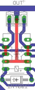
See underneath it that no solder bridges are formed, especially with the thin track that passes horizontally (bottom tracks depicted in blue). Retouch for cold joints.
See underneath it that no solder bridges are formed, especially with the thin track that passes horizontally (bottom tracks depicted in blue). Retouch for cold joints.
Attachments
Don't you sleep? 🙂 The relay is a 12v NEC one (orange in colour). I'm at work now so I can't be more specific - I bought the kit from somebody who said it was a teabag kit.
I remember looking at lots of pictures to decide which way round it went and settling with the solid line towards the IN4001 - could it be the wrong way round?
I measured with mV but I'll try with V when I get home and I'll check the joints but I remember being pleased with how it went in as I'm new to this (obviously) and it looked a neat job. I'll check again.
Thanks for your help.
EDIT - I'm pretty sure the relay is this one... http://www.newark.com/nec/ea2-12nu/signal-relay/dp/25M9064
Last edited:
... could it be the wrong way round? ... http://www.newark.com/nec/ea2-12nu/signal-relay/dp/25M9064
Looking at your picture at post #4331, your relay orientation is the same as mine and it's working in my case.
BTW, I also got my DCB1 kit from Teabag and I have exactly the same relay.
Good luck.
Thank you, that's good to know 🙂
I checked the soldering around the relay and I don't think I can improve on it. Picture attached (the whispy bits are from a cotton wool bud that I used to clean the board with alcohol and are gone now).
I tested those points with the DMM on V and the results are similar (e.g. 2.9 mV now flicks between 0.002 and 0.003). Are there any more checks I can do? Does the fact that plugging the right RCA in mutes both channels give any clues?
Thanks
Attachments
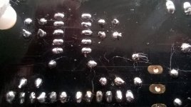
See its very clean with no whiskers at all. There are also solder bits to clean where the arrows show, especially where the right arrow is. The readings should have been many average mV in AC DMM mode when high music signal is playing but better try find a sinewave file so it will be steadier.
Attachments
Do those connections look that bad?
Sorry, I was reading DC. The lowest AC range that my DMM has is 200V with a resolution of 100mV so I suppose I can't check those voltages? I may have hit the buffers (no pun intended) with this. It's very demoralising.
EDIT: I found an old analogue meter with a 50V range and there's not even a flicker on any of the resistor legs.
Last edited:
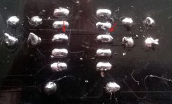
The right one especially might be a short. Make sure there are clean gaps between those joints and the thin lane that passes near them.
AC 200V range may still give readings, yes. BTW don't link more than 1200 pixels horizontal res images, they are unwieldy for this server to always resize and present proportionally.
AC 200V range may still give readings, yes. BTW don't link more than 1200 pixels horizontal res images, they are unwieldy for this server to always resize and present proportionally.
Do those connections look that bad?
Its not between the joints but it might be a short between the tin blobs and underlying copper lanes. You see them on the pic as patterns.
A regular line level signal shall be in the 1000 ACmV class so any of your DMM would get a reading. Its not the exact value that counts, only that its in the ballpark.
Sorry Salas, I've not posted pictures on a forum before. I won't put any more up until I know what I'm doing.
Thank you stajo, with the meter set to 200V (and 50V) I put black on the PSU 0V and red on each of the 220R legs in turn - zero on everything.
Is it likely to be a short around the relay? I cleaned up those two joints plus anything else that looked even slightly suspicious and moved the solder away from the thin tracks but nothing has changed.
Sorry Salas, I've not posted pictures on a forum before. I won't put any more up until I know what I'm doing.
Thank you stajo, with the meter set to 200V (and 50V) I put black on the PSU 0V and red on each of the 220R legs in turn - zero on everything.
Is it likely to be a short around the relay? I cleaned up those two joints plus anything else that looked even slightly suspicious and moved the solder away from the thin tracks but nothing has changed.
And (have to doublecheck;-) you had a signal of some sort (music, sinus...) going in to the buffer while measuring?
I did stajo - The Beatles - She Said She Said on an ipod, full volume on the ipod and DCB1. I've got a sinewave generator on this computer that I could use but didn't bother trying it while there was nothing at all being detected.
Try hook it up instead. Check DC offset first, and make sure you can hear the relay clicks also.
I did Salas, DC offset has been 1.5mV one side and 2.5mV on the other throughout my tinkerings but I checked it again and plugged it in. Great clean sound on one channel with one RCA plugged in and a low level sound on the other channel(??) but as soon as the ground sleeve of the other makes contact both channels are muted. The relay clicks when I turn the unit off.
I'll have to spend some time tomorrow methodically checking the effect of all RCA permutations. This has become a bit of a personal Everest! It's making me grumpy at the moment but I'll be a better person for it. Thanks to both of you for your help so far, it's very much appreciated.
I'll have to spend some time tomorrow methodically checking the effect of all RCA permutations. This has become a bit of a personal Everest! It's making me grumpy at the moment but I'll be a better person for it. Thanks to both of you for your help so far, it's very much appreciated.
Last edited:
Desolder the signal FET pair from the weird channel, measure their idss to make sure they are OK and put them back in mutually exchanged positions.
Hmm... time to call it a day I think and put this down as a fail for now, at least until I get to understand the circuit and the PCB a bit more and feel confident in doing things like testing jFETs and replacing components which looks unavoidable now.
As a summary, the wiring wasn't the problem (even without twisted pairs), a link from 0v on the board to chassis earth solved any ground hum problems, it could have been the relay, it could have been poor soldering on that and it could have been the jFETs not working, not having a suitable idss or not being in the best position. The kit labelled those two as 9.53 and 9.52 so perhaps I've broken one. And it appears that my DMM doesn't work for AC voltage 🙁
Thanks all for your help.
HI everyone...😱😱😱
My DCB1 have question.
It always fine.
But it's left no sounds.
What happen is it😕
My DCB1 have question.
It always fine.
But it's left no sounds.
What happen is it😕
Remote troubleshooting needs measurements data.
OK, Can you tell me, which one needs to measurement?
- Home
- Source & Line
- Analog Line Level
- Salas hotrodded blue DCB1 build