The first example of an amplifier with a complementary differential input to come to mind would be the Rotel RB-1080. Service docs e.g. at HFE, ET. It's not even an overly fancy topology, though it does use some really nice transistors.
Douglas, you are quite capable of doing this research yourself. Just type 'Stereophile' into Google and go to the reviews section.
..................................................
🙂
I don't believe that it's Mr. Self's position that is in need of support.
That problem was from the smps of the computer and it appear in the measurement chain.
Stereophile has the same problem with some of their testing.
Have you designed transformer amplifiers ? Are there data available on them ? Which transformers have you used ?
.
I did once design a mains synthesiser which was basically a 250W/8R audio amplifier driving a mains transformer secondary with output from the primary.
Worked very nicely, but then it did not have to operate above 60 Hz. I wouldn't recommend it for audio.
Douglas, what is the idle consumption of a 150W 8 ohm blameless amp?
This depends very much on what output stage you choose. With a single CFP pair output and 0R1 "emitter" resistors the quiescent current is about 15mA so the dissipation is about 1.5 Watts.
With a single EF pair output and 0R1 emitter resistors the quiescent current is about 200mA so the dissipation is about 20 Watts.
I am assuming you mean Class-B.
The dissipations for a 150W into 8r0 amplifier will be a but higher, since the supply rails will be about +-56Vdc, not the +-50Vdc expected for a 100W into 8r0 amplifier.
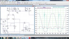
Mr. Self, I noticed that you use current limiting transistor to protect the EF-VAS in case of clipping.
My simulation shows that this is not enough to protect EF transistor from burning in case of severe clipping. Adding protection resistor between EF collector and the ground serves two purposes, protect EF transistor and vastly improves clipping behavior.
BR Damir
My simulation shows that this is not enough to protect EF transistor from burning in case of severe clipping. Adding protection resistor between EF collector and the ground serves two purposes, protect EF transistor and vastly improves clipping behavior.
BR Damir
Attachments

The dissipations for a 150W into 8r0 amplifier will be a but higher, since the supply rails will be about +-56Vdc, not the +-50Vdc expected for a 100W into 8r0 amplifier.
I'm not sure what allowances you're making for the internal losses of the amplifier, but I make it more like +/-52V for the stated conditions.
Adding more EF output pairs increases the quiescent proportionally, so the dissipation can be quite significant for a big amplifier. And this is optimal Class-B, not any sort of Class-AB.
Douglas, can you be more specific:
For a 150W RMS into 8Ohm amplifier
Supply voltage = ~±55V
Input diff current = 5mA
VAS current = 10mA
Drivers = 5mA
Output stage = 15mA
Or something similar
Thanks
Jens
Last edited:
Douglas, can you be more specific:
For a 150W RMS into 8Ohm amplifier
Supply voltage = ~±55V
Input diff current = 5mA
VAS current = 10mA
Drivers = 5mA
Output stage = 15mA
Or something similar
Thanks
Jens
More specific about what?
More specific about what?
Power consumption in the different sections of the blameless amplifier if it had been 150W /8Ohm capable
\\\Jens
looks like a 1pr CFP comes to something around 5W
Add on another 5W for the PSU and transformer and we end up with ~10W for a 150W amplifier.
Add on another 5W for the PSU and transformer and we end up with ~10W for a 150W amplifier.
looks like a 1pr CFP comes to something around 5W
Add on another 5W for the PSU and transformer and we end up with ~10W for a 150W amplifier.
?????? I said 1.5W for the CFP output stage.
As for the transformer, where does your 5W come from?
I'll try one more time before I start the simulator....
How much curret does the different sections in a blameless amp draw running from ±55V rails.
Input diff current = ?mA
VAS current = ???mA
Drivers = ????mA
Output stage = ????mA
Why is this a hard question?
How much curret does the different sections in a blameless amp draw running from ±55V rails.
Input diff current = ?mA
VAS current = ???mA
Drivers = ????mA
Output stage = ????mA
Why is this a hard question?
Jens.
I guess it depends on which year of blameless 😉. Higher rail voltages will increase the currents unless you size the bias resistors for the voltage references for the 55v rails. At 32v to 40v rails the input is 4-4.5ma vas 5-5.5ma and drivers in the ef version about 6-6.5ma. Output is whatever the vbe multiplier is adjusted to, as stable as a vbe multiplier isnt and will wander 😀.
ive been noticing much more as i read through the 6th edition one might need to keep in mind not everything is referred to as we might know it, eg what is commonly known as Phase Lead is called Input inclusive compensation here. My understanding on this has been that it is a way to bypass the output stage at high frequency where it starts to lag causing phase shift. Sizing is also dependent on whether or not the circuit is stable at unity at a low enough frequency, hence why sometimes a resistor is placed in series with this cap.
Colin
The Blameless' currents vary very little with changes in supply rail voltage.
Very different from some amplifiers that go haywire with voltage changes.
It's just a case of adding up the nominal current s that make up the total quiescent current and multiplying by the rail to rail voltage, assuming that the Power Ground carries nearly zero quiescent current.
DouglasSelf.
The 5W is a guesstimate based on the power draw of the transformer times it's own losses and some losses in the bridge rectifier/s.
Phase Lead is called Input inclusive compensation here. My understanding on this has been that it is a way to bypass the output...
The nomenclature matches Cordell's book, which has an nice introduction to the topic as well as some rather successful applications.
Rather than a way to bypass the output, it is a way to include the input in the Miller compensation loop, hence the name, naturally.
Best wishes
David
Last edited:
Why is this a hard question?
Because it was confusingly posed.
Your current estimates in post #209 are correct. Post #215 is incorrect because these currents are virtually independent of the supply rail. My amplifiers will give a visually OK sinewave down to about +/-2V, which means you can turn them on slowly with a variac and check all is well. This gives a great feeling of security.
Don't try that with some other designs.
Last edited:
The nomenclature matches Cordell's book, which has an nice introduction to the topic as well as some rather successful applications.
Best wishes
David
Some rather successful simulations, to be exact. There are no measurements of real amplifiers.
...There are no measurements of real amplifiers.
Yes there are. Bob's benchmark EC amplifier used this technique.
Published in JAES way back in 1984 Jan/Feb. and carefully measured.
He rather modestly claims only better than 0.0015 % THD at 20 kHz in the article but the presented data looks to be sub 0.001 %.
Some of the measurements are mentioned in the book, see p 257 for distortion, slew rate is earlier.
Best wishes
David
Last edited:
- Status
- Not open for further replies.
- Home
- Amplifiers
- Solid State
- Your opinions are sought on Audio Power Amplifier Design: 6th Edition. Douglas Self