... 47k is probably as low as you can go in practice but that makes the feedback resistor very high... high enough that noise can become an issue. Also the high values mean stray capacitance plays a part and that will be noticeable on testing with squarewaves.
...
Do you mean like this? Any effects on the high frequencies?
So:
pros are high input impedance
cons: even more hiss than now, bad scope wave/measurements
Attachments
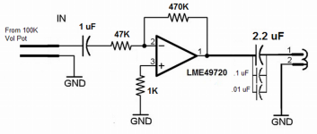
Yes, like that but it is far from ideal. The 47k determines the input impedance. The 470k feedback resistor is getting to the point where high frequency response will suffer... it certainly will when looked at in raw numbers such as rise time... but would cover the audio bandwidth and perhaps only be 1db or so down at 20kHz (at a guess... and its opamp specific for that). More hiss too.
I mentioned an active control but that has problems too with a one opamp set up so probably a non starter too.
(A non inverting stage would solve all your problems really and if it must be a one opamp design is probably the way to go).
I mentioned an active control but that has problems too with a one opamp set up so probably a non starter too.
(A non inverting stage would solve all your problems really and if it must be a one opamp design is probably the way to go).
I said 1 db down at around 20kHz, actually it will be a lot less than that, closer to 0.1db or lower.
Your apparent problems are solely due to adopting an inverting topology.
I am convinced 😀
If you all give me the best values for the resistors or add anything to the schematic, I will build it non-inverting. I have some play PCBs coming from China.
Game?
Resistors:
R1. =
R2. =
R3. =
Attachments
Move R2 to -IN Pin
Add R4 from left side of R1 to Signal Ground.
Add C3 from right side of R1 to Signal ground.
Add R5 from Left side of C1 to Signal Ground.
Add R6 from right side of C2 (2u2F) to Output Ground.
Add R4 from left side of R1 to Signal Ground.
Add C3 from right side of R1 to Signal ground.
Add R5 from Left side of C1 to Signal Ground.
Add R6 from right side of C2 (2u2F) to Output Ground.
Last edited:
One for tomorrow 🙂
Look up the non inverting configuration... you need to re-arrange the topology a little.
Edit... first out of the bag,
Non-Inverting Amplifier | Op Amp Circuit | Radio-Electronics.com
Look up the non inverting configuration... you need to re-arrange the topology a little.
Edit... first out of the bag,
Non-Inverting Amplifier | Op Amp Circuit | Radio-Electronics.com
Move R2 to -IN Pin
Add R4 from left side of R1 to Signal Ground.
Add C3 from right side of R1 to Signal ground.
Add R5 from Left side of C1 to Signal Ground.
Add R6 from right side of C2 (2u2F) to Output Ground.
Thanks, I will draw it up.
One for tomorrow 🙂
Look up the non inverting configuration... you need to re-arrange the topology a little.
Edit... first out of the bag,
Non-Inverting Amplifier | Op Amp Circuit | Radio-Electronics.com
Thanks, will look at these as well.
For now, the inverting pre is back to 10X gain, 10K input and 100K feedback resistors as of this writing. The hiss is not discernible from the listening position and is decreased considerably.
I know I may be biased, but this simple pre sounds quite good and has plenty of tight bass response. It is clean sounding, probably one of the cleanest sounding preamps I've heard. Generous in detail as well and very few things seem to escape its grip on the music if any at all.
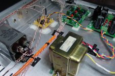
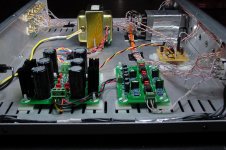
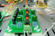
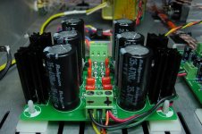
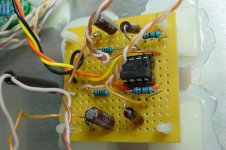
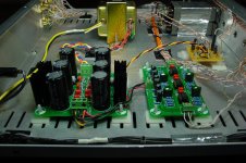
Final pics and schematic of the inverting pre follow for someone else to try. Not a big effort or many parts, plenty of payback.
I do wonder if these Rubycon caps in the power supply board are legit.
Thanks again.
Attachments

Hi,
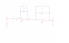
There is no need placing resistors between +In and Gnd-these are hum sources. The offset is no problem when talking about pre-stages.
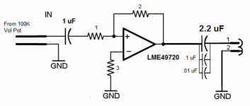
Also some small capacitors will turn inverting preamp in integrator for high frequencies and will stabilize the stage-please see the picture.
Ground decoupling by small resistor (5...20 Ohms) has it's own noise cancelation function too.
Of course, high impedance inverting circuit can be used to get desired amplification using 1 opamp.
Regards: Nick 🙂
There is no need placing resistors between +In and Gnd-these are hum sources. The offset is no problem when talking about pre-stages.
Also some small capacitors will turn inverting preamp in integrator for high frequencies and will stabilize the stage-please see the picture.
Ground decoupling by small resistor (5...20 Ohms) has it's own noise cancelation function too.
Of course, high impedance inverting circuit can be used to get desired amplification using 1 opamp.
Regards: Nick 🙂
Attachments
For now, the inverting pre is back to 10X gain, 10K input and 100K feedback resistors as of this writing. The hiss is not discernible from the listening position and is decreased considerably.
Well that's quite acceptable as a gain stage and the only real problem is the 100k pot working into the 10k impedance. You may notice the "feel" of the pot isn't quite right in that the apparent volume level doesn't seem to follow the mechanical rotation of the pot accurately... but that's no real detriment in itself.
Hi,
There is no need placing resistors between +In and Gnd-these are hum sources. The offset is no problem when talking about pre-stages.
Also some small capacitors will turn inverting preamp in integrator for high frequencies and will stabilize the stage-please see the picture.
Ground decoupling by small resistor (5...20 Ohms) has it's own noise cancelation function too.
Of course, high impedance inverting circuit can be used to get desired amplification using 1 opamp.
Regards: Nick 🙂
Well, to be precise - this is true for an ideal op-amp (spherical op-amp in vacuum 😛). However, a real op-amp has got certain input currents, and you may want to keep those currents equal at both inputs (at least to keep the low DC offset at the output and maintain overall balance of the circuit). Of course, this is less critical for high-impedance op-amps (e.g. with FETs at the input).
Cheers,
Valery
DC offset voltage will not be a problem in most cases when talking about audio pre-amps, but if it is, than opamp with balance-leads must be choosen,FET input as mentioned above or adding DC-servo to LME49720 will do the job. In LME49720's datasheet there is example of RIAA preamp in Fig.1 with 2 galvanically connected stages.
DC servo keeps offset minimal but as the same as a simple resistor from +In to ground, both are noise sources.
DC servo keeps offset minimal but as the same as a simple resistor from +In to ground, both are noise sources.
One last thought on the LME49720 inverting configuration preamp.
As you will recall, I have built two identical preamplifiers with this chip. I had to try different combinations of input and feedback resistors (aiming to stay at 10X gain) in order to cut down hiss and improve input impedance. Here is my experience:
Input/feedback resistor values:
10K / 100K: A good compromise for solid state power amp, not too much hiss, adequate treble- 10X gain
15K / 150K: More hiss, slightly better treble, better input impedance, well suited for tube power amp- 10X gain
47K / 470K: Too much hiss, great treble extension, but distractedly noisy- 10X gain
Overall I've kept the tube pre at 15K/150K and the solid state intended pre at 10K/100K combination.
Thanks for all the input, moving on to non-inverting...
Attachments
- Status
- Not open for further replies.
- Home
- Amplifiers
- Solid State
- Line Stage Preamp: need help eliminating nasty hum!