Oh, is that what it takes? '-)
Last I looked the claim was distortion inversely proportional to current and the load was still noted with a question mark! This is the kind of stuff the water powered cars folks do.
Last I looked the claim was distortion inversely proportional to current and the load was still noted with a question mark! This is the kind of stuff the water powered cars folks do.
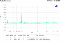
Scott here are FFT's of before and after abuse.
Test tones were 19,000 and 20,000 hertz both at .01 Volts. The source impedance was below 50 ohms the input impedance just a bit above 100,000 ohms. 0 dB is .01 volts. Result of a 32k FFT 1024 averages,
This is a twisted pair of 24 gauge magnet wire loosely twisted (about 4 turns to the inch). One trace is before additional twisting. It was then twisted and untwisted to about 8 turns per inch five times and then twisted back to the original 4 turns to the inch.
Now you said you were going to try this yourself. If you need some 24 gauge copper magnet wire just let me know and I will send you some.
If you have any other questions about the setup please ask.
Pavel do you still want to make a wager?
ES
Attachments
Last edited:
Any ideas about what's happening at and around 3K & 4Khz ?
Harmonic distortion probably in the AP. I sometimes get noise at 2.7 k. Don't know where it comes from. I think the skill in looking at any measurement is the feel for what is real or not.
Ed just to put another perspective on this unless this effect violates superposition, KVL, and KCL the measurement can be arranged to one measuring only the voltage across the wire. This eliminates the big confounder, the unknown residual from trying to look at the full excitation at the same time as the supposed distortion which also includes the uncertainties of drops in the grounding inside the instrument. The ante has been upped, now the distortion across the wire has a -100dB attenuation to overcome. Interestingly the distortion is now approaching 10's of % of the voltage across the wire.
BTW by symmetry only ½ the circuit needs to be measured.
BTW by symmetry only ½ the circuit needs to be measured.
Attachments
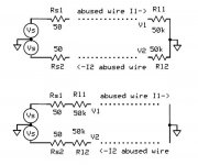
Ed just to put another perspective on this unless this effect violates superposition, KVL, and KCL the measurement can be arranged to one measuring only the voltage across the wire. This eliminates the big confounder, the unknown residual from trying to look at the full excitation at the same time as the supposed distortion which also includes the uncertainties of drops in the grounding inside the instrument. The ante has been upped, now the distortion across the wire has a -100dB attenuation to overcome. Interestingly the distortion is now approaching 10's of % of the voltage across the wire.
BTW by symmetry only ½ the circuit needs to be measured.
That is what my custom measuring device does. The issue was can you make a wire with enought defects it can be measured with off the shelf test equpment.
Scott
Would you care to guess what happens when I place a 1K load on the pair under test?
20 questions have returned, would you care to explore the alien signals from imperfect differential output and the grounding of the AP being used far beyond its specified noise/distortion floor (remember jn and JC's wire distortion controversy). As I just said this measurement does not require an AP or any instrument with low distortion at all.
A quick computation shows in the neighborhood of 100nV across the wires and by your scale factor -107dB re 10mV ~45nV or so distortion of this voltage (~50%).
Last edited:
The distortion drops to the baseline of the new cable.
My theory says at very low currents charge propagation has greater variance. Loading the signal source increases the current and the variance decreases. This is what I observe.
The source of distortion appears not to be thermal or even what is called voltage coefficient distortion. Nor do I think it is micro diodes.
You are welcome to do your own tests.
I don't think we have a basis to agree on this.
My theory says at very low currents charge propagation has greater variance. Loading the signal source increases the current and the variance decreases. This is what I observe.
I don't think we have a basis to agree on this.
No you observe something and refuse to examine effects that could contaminate the observed results. I suppose I will have to make a 50k resistor 1 Ohm of wire divider and observe nothing like Dimitri, what good will that do? Variance has nothing to do with distortion BTW, but you knew that.
Thank you Simon for the offer to play with your box, but I’m afraid that you will be disappointed with the results.I can lend you my version if you want to play. I have show others the setup and let them play. The results are consistent even over a few years.
the same applies to a series RL in parallel with a single resistor, the current "crowds" into the one resistor when the L blocks the fast current rise time
So skin effect SHUNTS inductance? Does this mean that if I maximize skin effect, I am actually reducing inductance? This means that in a wire, impedance vs F starts with 0 phase, then goes to 90 phase, then 45 phase with skin effect onset. IE skin effect only occurs while DC resistance is swamped by inductance.
Furthermore, would current crowding cause a change in inductance? Could nonlinear distortion here be attributed to a modulation in inductance? What are the phase of the harmonics relative to the fundamental? In a ground plane current density affects inductance, why not in a wire?
Also, what proportion of the skin resistance is nonlinear? It can't be completely nonlinear if it can be modeled well with linear components. So for instance what would be the THD of the wire current from a voltage source, how would it vary depending on frequency and signal level?
Thank you Simon for the offer to play with your box, but I’m afraid that you will be disappointed with the results.
PM me your contact info. I'll take the risk.
No you observe something and refuse to examine effects that could contaminate the observed results. I suppose I will have to make a 50k resistor 1 Ohm of wire divider and observe nothing like Dimitri, what good will that do? Variance has nothing to do with distortion BTW, but you knew that.
First of all using an unbalanced test puts you at a significant noise disadvantage.
Second I observe the results consistently, with different set ups and test equipment. I even show it to others and let them play.
Now as mentioned before the variance in propagation velocity shows up as distortion both by the nature of the measuring system and it does provide essentially a noisier output. I know you know what noise modulation looks like.
But you are welcome to do your best to prove a negative. 🙂
Last edited:
So skin effect SHUNTS inductance? Does this mean that if I maximize skin effect, I am actually reducing inductance?
See attachments
George
Attachments
Last edited:
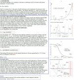
Thanks for that paper.
If we still can't model it without getting wormy deviations from the measured result, then I doubt we understand it enough to rule out nonlinearity based on the very math that's failed to model it without anomalies.
Are the models used in that paper compromised to provide computational expediance, or do they represent the best effort at modeling skin effect?
And 11 years ago, discussing a non peer reviewed magazine article from 18 years prior to that..sheesh.That was nicely circular. JN in another forum.
Just a filter. Can model approximately with inductors and resistors. Nothing nonlinear.
Yes, you can certainly model anything you want to using linear elements, then claim the modelled system is linear.
Hmmm. Did you just say "model approximately".
Self serving, and quite scientifically inaccurate methodology. I would never attempt to claim a system as linear by using linear elements to model it and getting a linear result. Even I'm more rigorous than that. Tis better to try to model reality no?
Strawman arguments don't work well with me.I cannot comment on how this fits with "pay grades" in other countries.
Harmonic distortion probably in the AP. I sometimes get noise at 2.7 k. Don't know where it comes from. I think the skill in looking at any measurement is the feel for what is real or not.
It is not correct to casually brush off parts of the resulting output by "feel", and embracing the part you wish. That's by no means scientifically accurate.
So skin effect SHUNTS inductance? Does this mean that if I maximize skin effect, I am actually reducing inductance?
Yes and yes. But recall, the inductance within a wire at DC is 15 nH per foot. At the hf limit, where all the current is on the outer surface of the wire, there will be zero internal inductance of the wire. A cylindrical shell of current has no internal magnetic field, hence no inductance.
Just remember though, at 20 Khz with a 1mm dia wire, the current at the center is still about 70% of the surface current, so the internal inductance really hasn't dropped off that much.
What are the phase of the harmonics relative to the fundamental? In a ground plane current density affects inductance, why not in a wire?
In a ground plane, current density and path affects inductance. A wide flat current has less inductance than a skinny one only because the wide one has a higher reluctance path for field lines.
jn
Last edited:
Now as mentioned before the variance in propagation velocity shows up as distortion both by the nature of the measuring system and it does provide essentially a noisier output.
OK, I'm stacking a couple of those new 1nV in-amps that should do nicely for a simple .7nV diff-amp. The above statement makes no sense to me at all, I must just be confused again. 🙂
OK, I'm stacking a couple of those new 1nV in-amps that should do nicely for a simple .7nV diff-amp. The above statement makes no sense to me at all, I must just be confused again. 🙂
When we look at a sine wave one axis is voltage the other is time. If you wiggle the time you get a distorted waveform.
Paralleling opamps I have found that when there is an output series resistor all of the opamps do not have the same output, there is a bit of variance mostly on DC offset.
When we look at a sine wave one axis is voltage the other is time. If you wiggle the time you get a distorted waveform.
Paralleling opamps I have found that when there is an output series resistor all of the opamps do not have the same output, there is a bit of variance mostly on DC offset.
Not op-amps, "Stacked Amplifiers Lower Noise" EDN 1982, you can combine instrumentation amplifiers via the REF pins.
Random time dither does not make harmonic distortion. In fact wiggle either axis (amplitude/time) randomly and you get randomly phased noise sidebands another thing not shown in your plot. The magnitude only FFT losses the phase information.
You show pure harmonics but talk about random variances.
- Status
- Not open for further replies.
- Home
- Member Areas
- The Lounge
- John Curl's Blowtorch preamplifier part II