So I've been semi-upgrading a pioneer SX-205. So far I've changed out all the 4558 op amps (ugh) and all the signal path capacitors with panasonic fc series ones. That's about it. Schematic here: http://diagramas.diagramasde.com/audio/PIONEER_SX205_SX255R.pdf
PSU caps are a no-go, size is impossible to find without downgrading the capacitance. Resistors would be a pain because when replacing the caps I found out the solder pads come off wayyyy to easily.
Any help is appreciated.
PSU caps are a no-go, size is impossible to find without downgrading the capacitance. Resistors would be a pain because when replacing the caps I found out the solder pads come off wayyyy to easily.
Any help is appreciated.
Mouser part number 667-ECE-T1KA822EA
Were the 4558's faulty? What have you replaced them with?
Solder pads come off due to soldering iron too cold and too long on the joint melting the epoxy. Speed is of the essence.
Were they all faulty? It is difficult to improve on a design by a major manufacturer.
Were the 4558's faulty? What have you replaced them with?
Solder pads come off due to soldering iron too cold and too long on the joint melting the epoxy. Speed is of the essence.
Were they all faulty? It is difficult to improve on a design by a major manufacturer.
So I've been semi-upgrading a pioneer SX-205. So far I've changed out all the 4558 op amps (ugh) and all the signal path capacitors with panasonic fc series ones. That's about it. Schematic here: http://diagramas.diagramasde.com/audio/PIONEER_SX205_SX255R.pdf
PSU caps are a no-go, size is impossible to find without downgrading the capacitance. Resistors would be a pain because when replacing the caps I found out the solder pads come off wayyyy to easily.
Any help is appreciated.
Panasonic Fc are good for power supply but not for audio instead for signal use Elna silmic,Nichicon muse or film type cap.
This is a fairly basic '90s unit with seemingly half-decent rail decoupling. There are only 3 4558s in sight - one in the phonopre (a plain ol' NE5532 should work well as an upgrade there, as would an LM4562), one as a unit-gain buffer after the source selector and in front of the volume pot (they're actually OK for that) and another as a unity gain follower / bass enhancer with highish impedances after the volume pot (eek).
The whole circuit of number 3 seems unwise to me. For one thing you pretty much have to stick with parts suitable for highish impedances (e.g. NJM4560, NJM4565, BA4560), and then it contributes a fair bit of noise, far more than the µPC4570 that follows in the power amp frontend. If you can live without the bass boost function, I'd just convert the circuit to unity gain (short C631/632) and slap something lower-noise in there. What value is the volume pot, I'm guessing 50k or 20k (hopefully not 100k)? Source impedance may be between ~0 and Rpot/4. Something with low input impedance distortion like NE5532 (maybe LM4562, mind current noise though) may be better suited than e.g. an NJM2068 in there.
Most of the upgrade parts have higher current consumption than the originals (@3.5 mA each). Make sure that none of the conponents in the +/- 12V supply are unhappy about that, e.g. that 220 ohm dropper resistor.
Not sure what else one could do. C305/306 could probably stand upgrading with some nice 220µ bipolars, assuming you can fit those in there. Also make sure that the speaker switch and relay contacts are still doing their job well.
What value are the emitter resistors, R369/R370? You can check emitter bias by reading off the voltage across R385/C381 and R386/C382. Do you have the version with 2SC5200/2SA1943 output transistors or the weaker one using 2SC5198/2SA1941?
Last edited:
Ok thanks for the mouser number but the caps have to be 30mm in diameter.
I replaced them all with opa2134 and opa2132 and lme49720 except the phono preamp. I probably made the wrong position choices, but they are all in dip sockets so if someone could suggest the order that would be great!!!!
As for the caps, I could have swore a forum said they were ok. Well, guess I redo all of them :/.
Pretty sure it's 50K, I'll see about doing that. The power is ok I'm pretty sure, the resistors get hot of course, but nothing degrading happens to them.
Relay and switches are doing fine, no sounds when they switch thankfully.
Emitter resistors are .33 Ohm 5W and I have the 2SC5200 version. There are four extra holes on the heatsink, would adding an extra stage of those help anything?
Mouser part number is wrong, they need to be 30mm
Guess I need to replace all the caps :/. and I thought it sounded good.
Replaced them all except phono pre with opa2134 opa2132 and lme49720. I probably have them in bad circuit spots, much appreciated if someone could say to get rid of them or where in the circuit they could go.
Power supply is fine with the new chips, resistors are .33 ohm 5W duals. I have the 2SC5200 version.
Thank for all the input!
Don't do more than what you think makes an awful lot of sense. It may get you into far more trouble with bad solder joints and lifted pads than it's worth. Cap upgrades may be "nice to have" but generally are by no means essential.Guess I need to replace all the caps :/. and I thought it sounded good.
Which one is where now (IC203, IC301, IC601)? Are these all you have?Replaced them all except phono pre with opa2134 opa2132 and lme49720. I probably have them in bad circuit spots, much appreciated if someone could say to get rid of them or where in the circuit they could go.
The LME49720 arguably would be most useful in the phonopre (IC201) or after the volume pot (IC601, ideally while changing the circuit to a plain follower).
OPA2132/2134 would work fine for the input buffer (IC203), though as mentioned this position is quite uncritical - source impedances are low, and there's not that much to drive other than the volume pot.
IC301 (the µPC4570C) is not one I'd swap out so lightheartedly, as it's in the power amp frontend. This already is a fairly low-noise part to begin with, so the OPAs are out. Basically you need low noise and a good amount of GBW here for good transfer linearity. LME49720 should generally work fine here, too, but so probably would NJM2068, NJM4580 or LM833.
What's the bias voltage say then? Should be about 26 mV. With pre-set (fixed) bias I wouldn't be surprised to see it being slightly non-ideal.Power supply is fine with the new chips, resistors are .33 ohm 5W duals. I have the 2SC5200 version.
Couldn't measure it because I couldn't find that resistor on the board for the life of me, but to fix that, would I replace R337/R338 to a say, a 2K pot and adjust?
I have a Pioneer VSA of the same vintage and every cap in the thing is an Elna of some flavor, personally i would leave it alone unless there is an issue.
Yes they were some general purpose series. I probably will leave it now that I put caps best for power in there. oh well, can't be worse that plain ol Elnas.
.
Not sure what else one could do. C305/306 could probably stand upgrading with some nice 220µ bipolars
I'm all for it, but can ask why the value doubles from the 100uF in the schematic?
An externally hosted image should be here but it was not working when we last tested it.
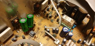
Put in the bipolars. They are huge and barely fit. I feel there is a definite sound improvement.
Hi Ivan,
I have also a Pioneer SX-205 RDS and I am thinking about upgrade it.
Unfortunately your picture in post #13 has evaporated so I don't know which bipolars you finally put there 100uF or 220 uF ?
Besides what else do you recommend to improve sound ( I mean "must be done" vs "good to have") ?
I have also a Pioneer SX-205 RDS and I am thinking about upgrade it.
Unfortunately your picture in post #13 has evaporated so I don't know which bipolars you finally put there 100uF or 220 uF ?
Besides what else do you recommend to improve sound ( I mean "must be done" vs "good to have") ?
Dang, it’s been years....
I would honestly say don’t bother working on it. It’s awful to work on and not that great of an amp. I was 17 back then and it was the only thing my parents had.
I would honestly say don’t bother working on it. It’s awful to work on and not that great of an amp. I was 17 back then and it was the only thing my parents had.
Yes, years are running fast.
But I can't say anything wrong about my SX-205 ( maybe I didn't hear others e.g. A-400).
Last year I had to replace a relay ( I put a goldplatted one)
so this year I am thinking about recapping. Any sugnestion is welcome.
But I can't say anything wrong about my SX-205 ( maybe I didn't hear others e.g. A-400).
Last year I had to replace a relay ( I put a goldplatted one)
so this year I am thinking about recapping. Any sugnestion is welcome.
Work done !
I have replaced:
IC301 from µPC4570C to LM 833
IC601 from NEC 4558 to LM 4562
and capacitors C305/C306 from electrolytic 100uF to bipolars 220 uF ( Nichicon Muse ).
Sound is much more detailed than before.
I had also a temptation to increase BIAS a little by replacing R337/338 into Bourns resistors but trying to measure voltage between emiters Q1/Q3 and Q2/Q4 ( they are connected with 2x0,33 5W resistors) result on my voltage meter when I switched on was 0 ??? Maybe after 10 min it would arise but I didn't know what caused that result. Maybe my meter is too cheap ( but it has 200 mV range) or measuring time was too short.
For the time being I put the cover back and enjoy with the sound.
On the picture there is new LM833 as well as new relay with gold connectors.
PS. in order to get to the bottom I do not disassemble all pcb but simply cut a hole with a Dremel angle grinder
Attachments
Now 2nd stage:
based on info in another forum I have replaced:
C301/302 from 2,2uF/25V electrolytics into polypropylens ( I have chosen 2,2uF/250V Mundorfs)
C303/304 from 470pF/50V ceramics into polystyrenes the same value
besides ( my idea as they were adjacent)
C383/384 from 100uF/25V into bipolars Nichicon Muse
C385/386 from ceramics 10nF to films
Honestly speaking sound improvement is minimal.
Maybe these Mundorfs are for speakers,
in other amplifiers I saw either WIMA MKT 2,2uF/63V ( tall 7x7x13mm)
or 2,2uF/250V Vishay MKT 1820 (light green)
This time I didn't grinded the bottom as in SM of SX-205 I saw a desription how to lift the PCB ( in SM of SX-205 RDS there's no such info)
Please have a look on the picture ( the small dark green are foil one and one polystyren is also visible.
Another stage will be PSU capacitors exchange from 6800uF/50V to 10000uF/71V and bridge rectifier from 4 amps to 6amps
Attachments

While waiting for capacitors and bridge rectifier I have connected headphones to a front socket. A hum or brum was heard (both channels)with potentiometer decreased to zero and no source connected. It was strange because I didn't hear that hum in speakers. So I connected headphones to speakers sockets ... and no hum ????.
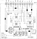
Why ? There are 2 resistors 330R/1W and 2 capacitors 3900 pF (schematic attached ) but I doubt they are transferring that hum because it is heard in both channels.
Please help !
Having access to speaker sockets I have measured a DC offset. In right channel it was stable -3,5 to -3,7 mV while in left channel the variance was from say -1,5 mV to -10 mV at the readings were jumping -2,2 to-3,5 to-7,2 to-1,1 to-2,5 to -3,7 to -10,0 and so on. It was even after 10 min of warming up with potentiometer at zero and no source.
Perhaps if DC offset is <50 mV it is OK but just for you to know that strange behaviour
Attachments
Jumping DC offset indicates high 1/f noise, quite possibly from a leaky capacitor. Would have to be either C305 or C301... you replaced those already, so hmm. Does shorting R301 make any difference? If that quietens things down, there may be a few more suspects, like Q1301.
BTW, when will people finally stop shoehorning these ginormous Mundorf film caps (intended for speaker crossovers) into circuits designed for puny little electrolytics? *sigh*
As for the hum problem, that's an interesting one. So the speaker test did not reveal hum but probably did reveal hiss, right?
All I can imagine is that there is some kind of issue with the routing of headphone ground. This seems to come from what I guess is a ground lug, KN4 (on SP SW ASSY). Not sure where that goes - screwed to chassis, and then returning to star ground via KN2 (on MOTHER ASSY)? I can only suggest to verify these connections (including good continuity KN2/KN4), and if that doesn't help, trying out some different routing, maybe a direct wire. I certainly don't see why the factory routing would be problematic though.
BTW, when will people finally stop shoehorning these ginormous Mundorf film caps (intended for speaker crossovers) into circuits designed for puny little electrolytics?
*sigh*As for the hum problem, that's an interesting one. So the speaker test did not reveal hum but probably did reveal hiss, right?
All I can imagine is that there is some kind of issue with the routing of headphone ground. This seems to come from what I guess is a ground lug, KN4 (on SP SW ASSY). Not sure where that goes - screwed to chassis, and then returning to star ground via KN2 (on MOTHER ASSY)? I can only suggest to verify these connections (including good continuity KN2/KN4), and if that doesn't help, trying out some different routing, maybe a direct wire. I certainly don't see why the factory routing would be problematic though.
Last edited:
- Home
- Amplifiers
- Solid State
- Upgrading Pioneer Amp