Hi Stephan,
Thank you for your response, I really appreciate that.
I have to dismantle the amplifier to take the measures and it will take some time.
So let me now explain the “Mundorfs case”
I was interested in upgrading Pioneer amplifiers and I red somewhere that Pioneer A-400 is considered to be one of 10 best amplifiers ever in the UK.
In one forum a guy suggested to:
replace coupling capacitors with polypropylene
replace feedback capacitors with either very high quality electrolytic like a Silmic II or my choice, a wet tantalum 😉 100uF is fine here but more the merrier
replace feedback bypass with polystyrene.
Also in Youtube there was a film ( from Polish service shop) where guy was repairing a potentiometer in A-400 ( it is a double one ) , then adjusted bias and at the end said that 2 capacitors have to be replaced into tall WIMA MKT.
Also in some class A amplifier projects those 2,2 uF capacitors are e.g. Vishay MKT.
But wanting to replace those 2,2uF to polipropylene I was looking for an audio MKP capacitor and found that most of them ( if not all) are big axial ones. So I have chosen those Mundorfs as they were smaller ( for 250V) and expensive which mean good ( at least for me)
Now I see that they gave no improvement and already 2 days ago I red in dyiAudio that you don’t like to put there capacitors intended for speaker crossovers.
– but what should I put there according to you ?
Do you agree that the 2,2uF capacitors are really important in amplifier circuit and there have to be something good placed ?
There are two other 2,2 uF C311 /312 should they also be replaced ?
The bigger the cap gets and the longer the leads to the final component are the higher is the risk of picking up noise and handle with instability/oscillation. If I would get something like this on my desk with pressed in caps like this I would throw it away...
As for the 2µ2-caps: Get some MKT/MKS with the right leadspacing and 40-63V-rating and it'll be fine.
As for the 2µ2-caps: Get some MKT/MKS with the right leadspacing and 40-63V-rating and it'll be fine.
Hum or buzz fixed thanks to Stephan - it was that ground lug KN4. A half turn of screwdriver was enough.
As to DC offset jumps - they are probably caused by bad solders - I will fix it with caps change to WIMA MKT as advised by nfsgame.
I will come back when PSU capacitors and Mundorfs are changed
As to DC offset jumps - they are probably caused by bad solders - I will fix it with caps change to WIMA MKT as advised by nfsgame.
I will come back when PSU capacitors and Mundorfs are changed
Project completed !
Let me summarize what was changed:
1. PSU rectifier bridge from 4A to 6A
2. PSU capacitors from Nichicon 2x6800uF/50V to Nichicon 2x 10000uF/50V
3. protection relay from silver Omron to gold Weidmuller
4. IC301 ( initial opamp in power amplifier) from µPC4570C to LM 833
5. IC601 ( opamp in volume assy) from NEC 4558 to LM 4562
6. coupling capacitors C301/302 from 2,2uF/25V Elna electrolytics into no name 2,2 uF/400V polypropylens (I put a socket there for testing and these sounded best IMO, Nichicon Muse bipolars were also good )
7. feedback capacitors C305/C306 from electrolytic 100uF to 470uF Elna Silmic II ( I put also a socket there for testing)
8. bias adjustment resistors R337/338 from normal 680 R into 2K Bourns variable resistors ( in fact 1K would be enough because I reduced resistance to ca 550R)
9. some other capacitors:
C303/304 from 470pF/50V ceramics into polystyrenes the same value
C385/386 from ceramics 10nF to films
10. adjusted bias voltage between emitter resistors to ca 26mV
measured radiator temperature ca 33 degrees Celsius
measured DC offset ca 3mV
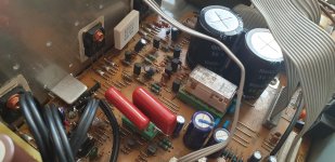
Since there was no room for bigger feedback capacitors and for variable resistors I made a kind of a balcony ( seen on a photo ). Wires coming out are thick because they are shielded.
My Pioneer SX-205RDS plays now great …as it used to.
Any comment welcome.
Let me summarize what was changed:
1. PSU rectifier bridge from 4A to 6A
2. PSU capacitors from Nichicon 2x6800uF/50V to Nichicon 2x 10000uF/50V
3. protection relay from silver Omron to gold Weidmuller
4. IC301 ( initial opamp in power amplifier) from µPC4570C to LM 833
5. IC601 ( opamp in volume assy) from NEC 4558 to LM 4562
6. coupling capacitors C301/302 from 2,2uF/25V Elna electrolytics into no name 2,2 uF/400V polypropylens (I put a socket there for testing and these sounded best IMO, Nichicon Muse bipolars were also good )
7. feedback capacitors C305/C306 from electrolytic 100uF to 470uF Elna Silmic II ( I put also a socket there for testing)
8. bias adjustment resistors R337/338 from normal 680 R into 2K Bourns variable resistors ( in fact 1K would be enough because I reduced resistance to ca 550R)
9. some other capacitors:
C303/304 from 470pF/50V ceramics into polystyrenes the same value
C385/386 from ceramics 10nF to films
10. adjusted bias voltage between emitter resistors to ca 26mV
measured radiator temperature ca 33 degrees Celsius
measured DC offset ca 3mV
Since there was no room for bigger feedback capacitors and for variable resistors I made a kind of a balcony ( seen on a photo ). Wires coming out are thick because they are shielded.
My Pioneer SX-205RDS plays now great …as it used to.
Any comment welcome.
Attachments

Hi to all,
Since this receiver is relatively tall I am considering inserting inside another power amp just for testing. New amp would use the same heatsink. But I don't want to destroy existing power amp but just switch it off. For signal it is simple - I can cut signal before coupling resistors R1305/1306 and after emiter resistors R369/370. But where should I cut the power supply ?
Your help or remarks are welcome !