Hey guys, i hooked up my modded yj black/blue board today and there was no sound going out of my speakers. No speaker pop, no hiss, no nothing. Board also doesnt get warm at all, like its not getting power at all. Im using a 19v 3.42a laptop brick for now. Unfortunately i was impatient and didnt test the board before i modded it so i dont know if it was broken from the get go. Any reasons why this is happening?
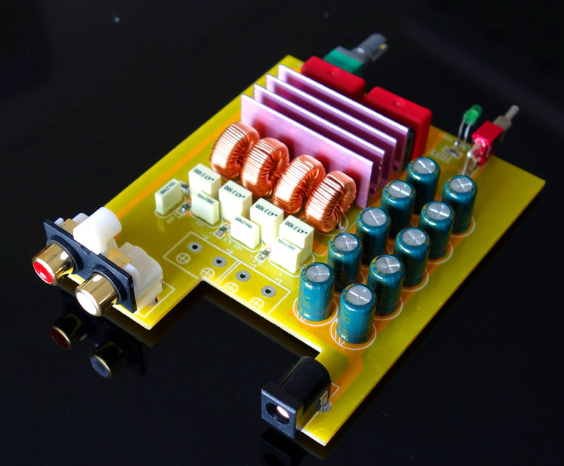
Electrolytics are mounted wrong way, they will blowup, marked side should be min, better wear glasses!!!!!!!!!!!!!!!!!!!!!!!!!!!!!!!!!!!!!!!!!
Last edited:
jeez THAT too! 😱 It's so difficult to see all on an upside-down image 😀Electrolytics are mounted wrong way, they will blowup, marked side should be min
To be clear, glasses to protect your eyes! Not because you made a mistake, I did many times 😀
Electrolytics are mounted wrong way, they will blowup, marked side should be min, better wear glasses!!!!!!!!!!!!!!!!!!!!!!!!!!!!!!!!!!!!!!!!!
Good catch - that is probably the reason and the caps are probably toast by now. 🙂
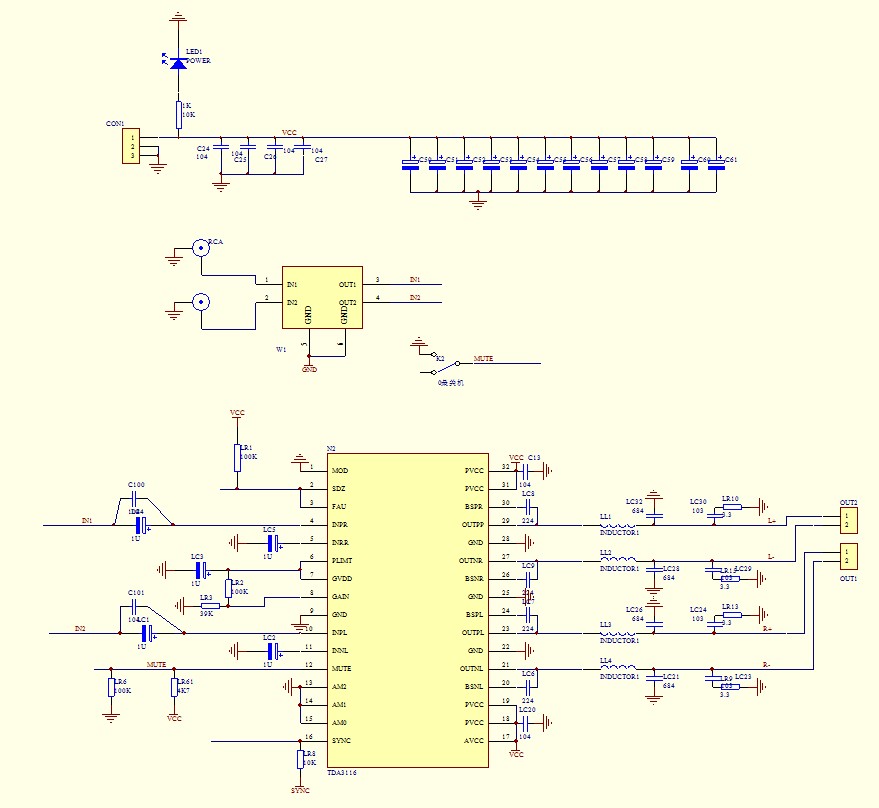
The 10nF and 3.3R is the post LC filter snubber. There is a pre-LC filter snubber that connects to the point between the chip output pin and the inductor. That snubber is in the EVM circuit and uses 330pF and 10R in series and R to ground. Where did you get the schematic?
Ah yes, I re-read your post and saw my mistake. You mentioned bootstrap snubbers of 330pf and 10R. I see it now, Between OUTPR and and BSPR on the TI chip. (Same for Left output and for Positive/negative) Thanks.
The schematic was on the ebay page for the board I got
Last edited:
Good catch - that is probably the reason and the caps are probably toast by now. 🙂
PSU capacitors could get hot too this way, been there 🙂, but maybe PSU was reversed too, then only ground was powered...
Last night I installed a large power cap to one of my boards, and the ringing got worse. It does seem that the ringing is caused by EMI noise from the output side.. Will the 330pF snubber filter remove/dampen some of that EMI?
Well the Amazon order went through anyway. They are one well oiled machine... I did get a message back from 'bangk' the seller, and they indicated that the amp is indeed the TPA3118 version. So I'll see what's inside when my package arrives tomorrow, and update the thread. Cheers!
Norwegian power is different I read once. Maybe ... Meantime I guess you did ground negative input somewhere? When chipdecoupling is close, 0.1uF, electrolytics do not have much influence on treble, or they do not in my situation that is.
Electrolytics are mounted wrong way, they will blowup, marked side should be min, better wear glasses!!!!!!!!!!!!!!!!!!!!!!!!!!!!!!!!!!!!!!!!!
Wow i feel stupid. Hopefully theyre still ok, im gonna put em in the right way and see what happens.
I really like these boards for modifying. I've completed 4 of them with only 2 in the graveyard 😱 My success rate with the Sure 2024 was less than 50%.
In order of building I have found that each one improved with the mods recommended in this forum, thanks to many of you 🙂
The first one was the YJ red board, then the YJ blue/black stock, then the YJ blue/black with modified input caps and power caps, then the same board with modified power, input, bootstrap caps and increased gain. At each stage I was pleasantly surprised at the improvements. 😀
I'm starting work on a 4.1 YJ board now and looking forward to hearing what it sounds like.
Thanks all 😀
Prezden, I have the same experience as you! 3/3 of boards are still alive^^ That Tpa chip is built like a tank! Did the increased gain have any positive effects on dynamics in your system?
I'm having a look at this image
An externally hosted image should be here but it was not working when we last tested it.and
the schematic drawingAn externally hosted image should be here but it was not working when we last tested it.
Looks like the output snubber is 4 10nF capacitors and 4 surface mount resistors (3.3 ohm i think)? I am a beginner at this! Surface mount scares me LOL
Based in the schematic they do parallel electrolitic CAP with the wima, once I read that this helps filtering noise, at both positive inputs, also use electrolitic at the negative input, wich I believe are not the best for that use. Beside this board its setup for a 32db gain. Also the switch at the front, is not a power switch, this might avoid the on/off pop bump, its for enable or disable the mute function. The rest seem identical to the schematic recommended by TI.
Based in the schematic they do parallel electrolitic CAP with the wima, once I read that this helps filtering noise, at both positive inputs, also use electrolitic at the negative input, wich I believe are not the best for that use. Beside this board its setup for a 32db gain. Also the switch at the front, is not a power switch, this might avoid the on/off pop bump, its for enable or disable the mute function. The rest seem identical to the schematic recommended by TI.
Yes, Danzz that is what I've noticed as well. Thanks!!
I'm also having trouble matching some of the components from the schematic to the actual board. The Capacitor array they have shows 12 in the schematic, but I count 10 on the board. and where are the bootstrap caps? Under the board maybe?
More pictures here but I dont see them
THE Latest 2 0 Hifi TPA3116 Digital Power Amplifier Board DIY KIT 50W 50W | eBay
They might be using small SMT bootstrap caps close to the chip and are hidden under the heatsink. It will not run without them, so rest assured they are there somewhere.
They might be using small SMT bootstrap caps close to the chip and are hidden under the heatsink. It will not run without them, so rest assured they are there somewhere.
Looks like they also skipped the 330pF snubber filter too.
Looks like they also skipped the 330pF snubber filter too.
As far as I know, SMSL is the only one implementing the bootstrap snubber circuit. Von Ah is getting one in a couple of days so he can confirm this and also tell is how good it sounds. It is a pretty attractive price for the 3118 amp considering the quality of the parts and the design of the box and circuitry. The YJ blue/black cost $27 with shipping and I have spent probably $12 in upgraded parts. $55 sounds like a great deal with case and power supply - iff it sounds good.
Last night I installed a large power cap to one of my boards, and the ringing got worse. It does seem that the ringing is caused by EMI noise from the output side.. Will the 330pF snubber filter remove/dampen some of that EMI?
I heard a lot of noise with both the black and blue stock board and the mod with four mundorf mcap 3.3uF input dc decoupling caps. Norway is known for its dirty power grid. BTW, I just saw a guy at Nasjonalteatern waiting for a train with a huge box saying KRELL. I scoffed a little.
I installed [...] Panasonic 3.3uF 250V metalized film caps for the input decoupling caps.
Just curious which particular model of Pany film caps you used?
I'm making up my own DigiKey order now.
A general question Regarding changing these input signal caps: stock is 1uF, though there have been a few reports of increased bass response with a bigger uF value (2.2 and 3.3 being common). Someone gave a good explanation several pages back as to why, if you change the cap value, you should do it for both the + and - side (not just the +, even though - just goes to ground).
Clearly what YJBlue did was use nicer film caps on the + side and cheaper/smaller ones on the - side. As the nicer film caps are kind of pricey, what's the minimum I can get away with for saving money on the - side? Is it sufficient to simply match capacitance? Or should I also match dielectric type and/or voltage as well?
I did not use anything fancy, just these 3.3uF 250V polyester film caps model ECQ-E2335KF from Panasonic (~$1 ea). Invalid Request
Here are the technical details and performance specs of this cap:
http://industrial.panasonic.com/www-data/pdf/ABD0000/ABD0000PE60.pdf
Seems like a good high value option with stable properties in the audio range and up to 60 deg C.
Folks say that both the neg and pos sides need the same capacitance so that the impedance to the input op amp is constant. I have been running with 3.3uF on the pos side and the stock 1uF on the neg-to-ground side and think its sounds pretty good. I have bought more of these 3.3uF caps and at a $1 ea they are not too bad for installing in the other spot. It seems that if the caps are matched to same type the characteristics for a balanced input will be optimal. Certainly it leaves the option open for future true balanced inputs for use with pro audio XLR inputs by breaking the grounded connection on the neg cap.
Last edited:
- Home
- Amplifiers
- Class D
- TPA3116D2 Amp